Continue to Site

Welcome to our site!

Electro Tech is an online community (with over 170,000 members) who enjoy talking about and building electronic circuits, projects and gadgets. To participate you need to register. Registration is free. Click here to register now.

  • Welcome to our site! Electro Tech is an online community (with over 170,000 members) who enjoy talking about and building electronic circuits, projects and gadgets. To participate you need to register. Registration is free. Click here to register now.

Laser or IR beam alarm system

Status
Not open for further replies.

zachtheterrible

Active Member
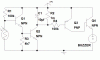
This is a cool little circuit that i made for a school project. It can be used as one of those things that is usually seen on the door of small shops so that when someone walks in it goes "ding dong". It could also be used as a burglar alarm (just need to get a loud enuf siren).

A light has to be pointed at the LDR. It can be anything, just as long as its bright enough. Im pretty sure that an infrared LED would work, a regular light, or my personal favorite: a laser pointer, just like in the movies 8) . You could encircle your house w/ a laser so wen someone crosses the beam you know.

R1 can be adjusted for sensitivity of the circuit to light. The lower R1, the more sensitive, and vica versa. The value of R1 will not allow the circuit to work in direct or indirect sunlight. R1 would have to be increased to make the circuit less sensitive to light (even then i doubt it would work in direct sunlight). An alternative to this is putting a tube on the LDR that is a couple centimeters long so that only light from the light source could get in.

R4 can be adjusted for how long the buzzer stays on. 100k makes it stay on for about 9 seconds. Or the value of C1 could be adjusted.

Someday i plan on putting a transmitter on the circuit so that it could be put out in the yard, and a receiver inside would go off. HAVE FUN :lol:
 

Attachments

  • beam_alarm1.gif
    beam_alarm1.gif
    14.8 KB · Views: 16,611
Help Please!

Pretty nice design. I made one myself but it only has three components. A resistor, transistor, and a photo transistor. I wired it so that I have an input of 220watts and an output of 220watts(so I can use either a radio or a lighting fixture or any appliance running in 220watts) I've been having loads of fun with it but there's just one problem. It turns off as soon as you leave the beam so I want to install a time switch and have it run for a few more seconds after its turned on. Can you help me? I don't know what to add to give it that effect.
 
you're using it as an alarm, so that when someone crosses the beam the radio or whatever will turn on, right?

Well, thats the whole point of my design is to have a buzzer stay on for a couple of seconds after the beam has been crossed. Just use a power mosfet, or something that can handle 220 watts in place of Q4.
 
hi

could you give me a schematic diagram or anything that i could photocopy in a photoPCB so that i could make also a project.thank u
 
Personally, I would use a 555 wired in a monostable (one-shot) config and use a potentimeter to control time delay... Not sure if this design would have any benefits but I thought it would be worth mentioning.

Cheers.
 
theinfamousbob said:
Personally, I would use a 555 wired in a monostable (one-shot) config and use a potentimeter to control time delay... Not sure if this design would have any benefits but I thought it would be worth mentioning.

Cheers.

dont let me stop you :lol:
 
Re: hi tumor babalusay air

jawpring said:
could you give me a schematic diagram or anything that i could photocopy in a photoPCB so that i could make also a project.thank u

hoy edison tilan samet pappapanamon nga site pra lang makakita ng project ha...hehe gagooooooo..tukmol
 
How long do those cheap laser pointers last? The control circuitry is just a simple resistor and I'm worried about the diode burning out if I plug it in 24/7. Otherwise I'd like to make up a simple light beam trip wire myself.
 
what would you suggest for a reciever so you could recieve a signal inside i kinda need to do something like that.

thanks
 
Wow, i havent gotten any comments on this in a month or so and then BAM, 4 comments :lol:

could you give me a schematic diagram or anything that i could photocopy in a photoPCB so that i could make also a project.thank u
I am very sorry for not answering your question earlier jawpring. Unfortunately I cannot give you the PCB because it is in the .bmp format, and i convert it to .gif, the size changes, rendering the PCB useless. Very sorry about that :cry:

How long do those cheap laser pointers last? The control circuitry is just a simple resistor and I'm worried about the diode burning out if I plug it in 24/7. Otherwise I'd like to make up a simple light beam trip wire myself.
Just as long as a regular LED would, which is very very long :lol:

what would you suggest for a reciever so you could recieve a signal inside i kinda need to do something like that.
I don't really know what you mean. Define receiver, my circuit, the light dependent resistor, do you want to make some sort of wireless system . . .???
 
what would you suggest for a reciever so you could recieve a signal inside i kinda need to do something like that.
I don't really know what you mean. Define receiver, my circuit, the light dependent resistor, do you want to make some sort of wireless system . . .???

yes, in the original post you say that some day you would like to put it in the yard and have a reciver in the house, i was wondering if you could suggested a way to do this.
 
Oh, yes, well that would require a transmitter and receiver, and an encoder and decoder. I am working on that for a security system for my house, ill post a schematic maybe tomorrow, gotta leave for work right now, and then im going straight to the new star wars at 12:01AM, no time right now :lol:
 
Needs HElp

I am a lunatic at this but i'm a beginner 2 :idea: . so if you dont mind i need to know where the (-)terminal of the battery fits in :cry: . Its being a bit of a problem for sometime to me. But coudnt find an answer. 1 more thing why is the earthing neccessary and is it important and how can i do it.
:p Please email to me to Buddhika_karunathilaka123@yahoo.com.
Thank You.
Buddhika :?:
 
Re: Needs HElp

Buddhika123 said:
I am a lunatic at this but i'm a beginner 2 :idea: . so if you dont mind i need to know where the (-)terminal of the battery fits in :cry: . Its being a bit of a problem for sometime to me. But coudnt find an answer. 1 more thing why is the earthing neccessary and is it important and how can i do it.
:p Please email to me to Buddhika_karunathilaka123@yahoo.com.
Thank You.
Buddhika :?:

the -ve of the battery is the ground point shown in the figure . just connect the -ve point of batt: to that point. The ckt does not need an earthing
 
You Might take a look at the Laser alarm circuit on my website.

**broken link removed**

It works quite good.
 
Status
Not open for further replies.

Latest threads

Back
Top