Continue to Site

Welcome to our site!

Electro Tech is an online community (with over 170,000 members) who enjoy talking about and building electronic circuits, projects and gadgets. To participate you need to register. Registration is free. Click here to register now.

  • Welcome to our site! Electro Tech is an online community (with over 170,000 members) who enjoy talking about and building electronic circuits, projects and gadgets. To participate you need to register. Registration is free. Click here to register now.

W005G Bridge Rectifier

Status
Not open for further replies.

Reynard

New Member
Hi all

i got a Fairchild W005G Bridge Rectifier which has 4pins (+, - and 2 ~ pins). I have also attached the datasheet for this particular IC.

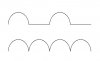
My aim is to get a full-wave rectifiied signal from a sine wave. So how should i connect the input sine wave (in terms of the IC pins) and how to i get the full-wave rectified signal that i want?

Cheers.
 

Attachments

  • Bridge Rectifier (Farnell 1017874).pdf
    45.7 KB · Views: 344
the AC/sine wave goes to ~ pins. There is a voltage drop across the diodes(1v in specs), so you won't get a completely accurate fullwave rectification from a simple bridge rectifer. If the signal is small you may need to use an op-amp based rectifier.
 
If you want less voltage drop across a bridge rectifier you may have to build one with 4 germanium diodes which have only a voltage drop of 0.3 volts across each diode.
Otherwise you have to use an opamp too as already suggested.
 
Paul Obrien said:
the AC/sine wave goes to ~ pins. There is a voltage drop across the diodes(1v in specs), so you won't get a completely accurate fullwave rectification from a simple bridge rectifer. If the signal is small you may need to use an op-amp based rectifier.

Hmm....so is it right to input the sine wave into the 2~ pins and get the wanted rectified signale from the + and - pins?

Will such a W005G bridge rectifier provide a half-wave or a full-wave rectifier?

Cheers
 
Full wave.
In your case 100 or 120 Hz with all the sine waves on one side of the nil axis.
depending weather you are in a 50 or 60 Hz country.
 
RODALCO said:
Full wave.
In your case 100 or 120 Hz with all the sine waves on one side of the nil axis.
depending weather you are in a 50 or 60 Hz country.

Hi

hmm seems like i can only get a half-wave rectified waveform from a sine wave. I input a sine wave into the 2 ~ pins and the oscilloscop probes to the + and - pins and only managed to get a half-wave.

Can any experts help me to get the full-wave rectified waveform?

Cheers
 
So you're seeing something similar to the first waveform below?
 

Attachments

  • full-wave.JPG
    full-wave.JPG
    14.2 KB · Views: 274
Hi, Reynard,

Refer to this website for information: **broken link removed**
 
You probably have a sine-wave generator with one of its output wires grounded. Then only half of a bridge rectifier works and the output is half-wave rectified. A Full-wave Rectifier Circuit using opamps will make full-wave rectification.
 
audioguru said:
You probably have a sine-wave generator with one of its output wires grounded. Then only half of a bridge rectifier works and the output is half-wave rectified. A Full-wave Rectifier Circuit using opamps will make full-wave rectification.

What! - you mean he's using an earthed scope, so it won't work? - no such problems with my scopes! :D :D :D :D :D
 
Acutally i don't quite get what you are meant by my signal generator being grounded... I think i will be clearer if some1 can provide me a simple circuit diagram showing me how to connect up to get a full-wave rectified waveform.

Thxs in advance
 
Reynard said:
Acutally i don't quite get what you are meant by my signal generator being grounded... I think i will be clearer if some1 can provide me a simple circuit diagram showing me how to connect up to get a full-wave rectified waveform.

Here's what happens when you connect your grounded generator, and grounded scope, to the bridge rectifier. Notice the dotted connection, that's the ground connection in your house between the two sockets, it shorts out the bottom left diode of the bridge.
 

Attachments

  • scope_ground.GIF
    scope_ground.GIF
    2.8 KB · Views: 195
Hi

thxs for all the help. I managed to get a fully rectified waveform when i use a battery power supply to operate the waveform generator. Think as long as the generator and the oscilloscope are not from the same ground, i will get the fully rectified waveform.

Cheers
 
Status
Not open for further replies.

New Articles From Microcontroller Tips

Back
Top