Continue to Site

Welcome to our site!

Electro Tech is an online community (with over 170,000 members) who enjoy talking about and building electronic circuits, projects and gadgets. To participate you need to register. Registration is free. Click here to register now.

  • Welcome to our site! Electro Tech is an online community (with over 170,000 members) who enjoy talking about and building electronic circuits, projects and gadgets. To participate you need to register. Registration is free. Click here to register now.

audio power bridge amplifier

Status
Not open for further replies.

arivel

Member
Hello everybody .
I'm about to make a very specific request, I need help
to understand if it is a feasible idea as I thought it and try to complete the circuit.
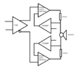
as the title suggests it is an audio power amplifier, the image you see is not to be considered a diagram because other components are missing but it serves as an aid to understanding what I want if words were not enough.
we see an FDA driving 2 bridged power audio chips, the feedback of the latter is made by 1 opamp per branch instead of the usual 2 resistors in series that go to ground.
this feedback must have a precise function, the
loudspeaker current drive .
the concept is to increase the voltage of the amplifier when the impedance of the loudspeaker increases in order to obtain a balance and a constant current, the task of the 2 resistors in series with the loudspeaker, with a value equal to 0.1 Ohm or even less , is to allow the 2 opamps to create a feedback . when the speaker impedance increases the voltage across the 2 resistors decreases and at that point the 2 opamps via feedback must increase the output voltage of the 2 bridged power chips.
why bridge? . because I can get twice the voltage of a ground loop amplifier.
without a bridge and with ground reference it is easier to do , but not with this system .
let's see if in this forum [unlike others] there are people able to succeed in realizing the scheme.
 

Attachments

  • amplificatore a ponte.png
    amplificatore a ponte.png
    37.2 KB · Views: 137
If the +ve amplifier is controlling the current, and the -ve amplifier is also controlling the current, you have two separate controls with only one variable, and it won't work. Component tolerances will mean that one amplifier will try to make more current flow than other one, and you will get a fight between one controller and the other.

If you want to run the amplifier in a constant current mode, you should have one op-amp measuring the current, and then compare that with the input. The result would be a voltage, which should be split and fed to the two amplifiers as a voltage set-point.
 
I do not agree .
the fact that the components of the two legs cannot be identical will result in two slightly different voltages at the output of the two power amplifiers and nothing else
 
I do not agree .
the fact that the components of the two legs cannot be identical will result in two slightly different voltages at the output of the two power amplifiers and nothing else
Well the devil is in the detail, and it depends on the gain of the amplifiers.

If you have a circuit that can increase the voltage across the speaker by 10 V if the current in the speaker is too small by 1 A, each half of the circuit will increase the voltage by 5 V in response to the 1 A change.

It then follows that if there is a 1 A measurement difference between the two amplifiers, then the voltage would be 5 V higher on one side than the other.

The values of the gain and the measurement errors will affect how big the offset is. The more tightly controlled the current is, the more accurate the current measurement has to be between the two sides.
 
An audio power amplifier is designed to have a flat frequency response with an extremely low output impedance to damp speaker resonances. It is a signal voltage source.

Your idea is to use current sources to drive the speaker with a high output impedance. Then the speaker will sound like a bongo drum at its low resonant frequency and the high frequency response will increase at high audio frequencies due to the speaker inductance.
this gentleman is called Joe Rasmussen and he is certainly not the latest arrival. is related to the project below:
he uses something different from what I propose, an amplifier
to transconductance.
a kit that costs $3,000.
I don't think he worked that hard on this project to make it sound like a bongo drum.
 
The Rasmussen article shows an expensive but ordinary speaker, not a current-source audio amplifier.
ALL audio amplifiers are a voltage source with an extremely low output impedance. The specification is called "The Damping Factor". An expensive Crown amplifier has a damping factor of >1500 for its extremely low output impedance:
 

Attachments

  • Crown amplifier damping factor.png
    Crown amplifier damping factor.png
    29.8 KB · Views: 120
  • damping_factor.pdf
    62.2 KB · Views: 142
The Rasmussen article shows an expensive but ordinary speaker, not a current-source audio amplifier.
ALL audio amplifiers are a voltage source with an extremely low output impedance. The specification is called "The Damping Factor". An expensive Crown amplifier has a damping factor of >1500 for its extremely low output impedance:
 

Attachments

  • Trans_Amp_Schema_Wiring_Caution.gif
    Trans_Amp_Schema_Wiring_Caution.gif
    25.9 KB · Views: 128
The 0.33 ohms resistor on the amplifier is a simple passive current limiter that reduces the maximum undistorted output power and softens clipping.
 
The 0.33 ohms resistor on the amplifier is a simple passive current limiter that reduces the maximum undistorted output power and softens clipping.
I know of two methods for driving a loudspeaker with current. that of using a transconductance amplifier and that of using a normal amplifier with a voltage output but with a very small resistance in series with the loudspeaker so as to create a feedback which modifies the amplitude response of the amplifier according to the impedance value of the same speaker.
 
I know of two methods for driving a loudspeaker with current. that of using a transconductance amplifier and that of using a normal amplifier with a voltage output but with a very small resistance in series with the loudspeaker so as to create a feedback which modifies the amplitude response of the amplifier according to the impedance value of the same speaker.
Remember vasccum tube amplifiers? Most of them had an output impedance that matched the speaker impedance. Then the power into the speaker depended on the higher impedance resonances of the speaker to cause "one note bass" like a bongo drum and a messed up high end.

Your idea of using "a current amplifier" instead of using a modern voltage amplifier causes the resonances of a speaker to have more voltage therefore have more output level. We don't want that, we want a flat frequency response from a speaker.

Modern solid state amplifiers have an extremely low output impedance (0.005 ohms) so that a modern speaker plays exactly what the voltage signal does.
 
As Ag notes, modern speakers are designed to have their flattest frequency response with a low impedance voltage source.
Any type of current out amp will have a higher output impedance that will cause the speaker to have a poor response with frequency.

The Rasmussen design amp has a high output impedance amp and won't work well with standard speakers.
 
You could have a full bridge amp with worse signal to noise ratio and THD specs than a half bridge with the same power and by the nature of those specs it absolutely wouldn't be as clean a signal. But the same is true the other way around as well.
momix
myindigocard
 
Last edited:
As Ag notes, modern speakers are designed to have their flattest frequency response with a low impedance voltage source.
Any type of current out amp will have a higher output impedance that will cause the speaker to have a poor response with frequency.

The Rasmussen design amp has a high output impedance amp and won't work well with standard speakers.
this can only be said after listening to his system , don't you think ?
 
The old lady who lived near my home blasted her TV very loud because she was deaf. It was cheap therefore its amplifier had a high output impedance and the speaker was also cheap so it had a high resonant low frequency and also had a lot of high frequency cone breakup problems. It sounded awful. A Rasmussen designed amp would produce the same problems.

ALL modern audio power amplifiers have an extremely low output impedance so that they are a voltage source that produces a flat frequency response into a modern speaker.
 
We already know that it will sound awful without hearing it.
But everybody is different. Many speakers are different. Some people are tone deaf then all sounds are the same to them.
Many people cannot hear high audio frequencies where woofer cones cause breakup peaks.
 
Status
Not open for further replies.

Latest threads

New Articles From Microcontroller Tips

Back
Top