Continue to Site

Welcome to our site!

Electro Tech is an online community (with over 170,000 members) who enjoy talking about and building electronic circuits, projects and gadgets. To participate you need to register. Registration is free. Click here to register now.

  • Welcome to our site! Electro Tech is an online community (with over 170,000 members) who enjoy talking about and building electronic circuits, projects and gadgets. To participate you need to register. Registration is free. Click here to register now.

Voltage spikes and dead MOSFETS

Status
Not open for further replies.
Hi,

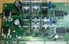
I am having trouble with my brushless DC motor controller board.
It is working perfectly for a period of time, and then (after few minutes), when i start to move electric vehicle, mosfet and mosfet driver explode. I dont know who is the first one to fail.
I have limited current to 20A (mosfet can resist up to 100A), so i dont think this is the problem.
Maybe the problem is some voltage spike that burn the mosfet down

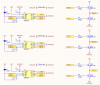
Im using MIC4604 with 4.7uF capacitors for gate charging and PSMN3R9 mosfets with 68ohm gate resistance.
Battery voltage is 24V (which is significuntly lower than mosfets 60V...)

Why does it burn down? Do i have to put some diodes to block that voltage spikes? How?

Please help me :)
 
What heatsinking are you using?
 
This one. You can also see burned mosfets and mosfet drivers (without heatsink)
 

Attachments

  • 20170221_115409-1.jpg
    20170221_115409-1.jpg
    1.1 MB · Views: 232
Do you have a suppression diode across the motor terminals?
 
No.. Ill show you the schematics now.
So you say i need something like in this picture? Diodes across all mosfets? Which ones do you recomend for this application?
 

Attachments

  • 1.PNG
    1.PNG
    66.8 KB · Views: 198
  • 2.jpg
    2.jpg
    14.1 KB · Views: 188
If motor is being driven by a MOSFET bridge, then it doesn't need added diodes.
The substrate diodes serve that purpose.

How did you limit the current to 20A?
 
The sop8 MIC4604 are half bridge MOSFET drivers with programmable gate driver, may want to check the gate drive set up on those IC's, or the one driving those problematic FETS.

:Edit: Were the Bootstrap Capacitors removed due to the damage prior the photo? Or have they not been installed before using the Driver board?

Datasheet states they are required.
 
Last edited:
Re read, more awake this time, I see you stated 4.7uF caps as the Gate charge.. I went the term of Bootstrap in place of the term Gate charge based on the image (post#3) more than, and the datasheets terminology. My bad.
 
The damage to the MOSFET looks typical of over-temperature. The damage to the gate diver is collateral I would say.

From your picture the heat-sinking looks inadequate.

Also the PSMN3R9 NMOSFET has an insulated case while the IRF3205 case is not insulated. It is not clear to me which NMOSFETs you are actually using, but if the meatsinks on the printed circuit board are not floating, the IRF3205 will cause a problem.

A 68 Ohm gate resistor sounds high for this application, around 10 Ohms would be expected.

Also, I am not sure that the gate driver is up to the job, but I have not analyzed the circuit in detail.

spec
 
A very common problem in bridges is cross-conduction between top and bottom Mosfets.

How are you preventing that? Do you have dead time between the two?
Also all the gate resistors should have a diode in parallel (anode facing the gate) such that the Mosfet turns off faster than it turns on.
 
Aren't fast recovery diodes recommended for use with the bootstrap capacitors? The LL4007 used at D1-3 is sluggish.
This Fairchild App Note is worth a read.
 
Last edited:
The sop8 MIC4604 are half bridge MOSFET drivers with programmable gate driver, may want to check the gate drive set up on those IC's, or the one driving those problematic FETS.

:Edit: Were the Bootstrap Capacitors removed due to the damage prior the photo? Or have they not been installed before using the Driver board?

Datasheet states they are required.

I removed 470uF capacitors (the big ones on the board), but others are 4.7uF which in my opinion is good value, not too big or too small.

The damage to the MOSFET looks typical of over-temperature. The damage to the gate diver is collateral I would say.

From your picture the heat-sinking looks inadequate.

Also the PSMN3R9 NMOSFET has an insulated case while the IRF3205 case is not insulated. It is not clear to me which NMOSFETs you are actually using, but if the meatsinks on the printed circuit board are not floating, the IRF3205 will cause a problem.

A 68 Ohm gate resistor sounds high for this application, around 10 Ohms would be expected.

Also, I am not sure that the gate driver is up to the job, but I have not analyzed the circuit in detail.

spec

I'm sorry about confusion there, mosfet on my boards are PSMN3R9 and not IRF3205 that says on schematics. But both of them are NOT insulated (drain is connected to the case), but i insulated it with silicone and plastic below the screw head. I checked if drain and heatsinks are not connected, and they are not. So that was not the problem.

68ohm gate resistor may be the problem but when i put 0ohm or 10ohm, mosfet driver burned down maybe because of too high current to gates (more than 1A). But on the other side, i read that 10-100ohm gate resistor is fine..
 
Status
Not open for further replies.

Latest threads

New Articles From Microcontroller Tips

Back
Top