Continue to Site

Welcome to our site!

Electro Tech is an online community (with over 170,000 members) who enjoy talking about and building electronic circuits, projects and gadgets. To participate you need to register. Registration is free. Click here to register now.

  • Welcome to our site! Electro Tech is an online community (with over 170,000 members) who enjoy talking about and building electronic circuits, projects and gadgets. To participate you need to register. Registration is free. Click here to register now.

Mosfets drain (n type the tab on to-220 mosfets)

MrDEB

Well-Known Member
I want to attach all 8 tabs to the circuit board as heat sink but can I attach all 8 on together on the circuit board?
 
In the NMOS TO-220 package the middle pin and the tab are connected to the drain. Connecting all of the drains together might be a suboptimal idea.
 
With 8 tabs?
1711160326124.png
 
I think I can translate this...

"I have a PCB that has 8 IRLZ44 TO-220 N-chan mosfets on it. I want to use the PCB as a heatsink. Can I connect all of the TABS together?"

Your answer is in post #3. Since the TAB and drain are connected together on the TO-220 package, connecting all the TABS together would connect all the drains together.

I don't think that matches your schematic very well (which others will have to find after enlisting the help of the Easter bunny).
 
Ok, I must admit I thought this was a ridiculous question at first read. But I do know that MrDEB is working on a project with a bunch of MOSFETs on a board, so I understand this "we join this question in progress" question.....

MrDEB wants to know if he can attach 8 MOSFETs to a common copper area on a circuit board. The answer involves knowing what the tab is connected to. And actually, datasheets are surprisingly UNhelpful in this regard.

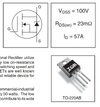
As far as my 4am brain and eyeballs can determine, nowhere does this datasheet actually say which pin is which or what's connected to the tab.

SmartSelect_20240323_043116_Edge.jpg

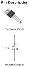
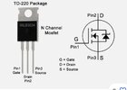
These two examples are better, showing the pinout but nowhere (again, blurry brain) do the datasheets explicitly state what's connected to the tab. If you're familiar with the TO-220 package, you'll know that the center pin connects to tab, but it would be nice if the datasheet confirmed that.

SmartSelect_20240323_043313_Edge.jpg

SmartSelect_20240323_042350_Edge.jpg

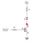
So, as stated above, pin 2, the drain, connects to the tab. If you want ANY MOSFET to turn on ALL the LEDs, this would work great! :)

SmartSelect_20240323_042238_Edge.jpg

But what you can do for some heatsinking is connect each MOSFET to an isolated copper area. Make sure the footprint has a pad for the tab (i.e. no soldermask) and if you can include a copper area on the bottom of the board, stitch top and bottom together with vias.
 
tumbleweed beat me to it!

Yes, I know my wordy explanation will be ignored, but I tried.
 
I'm not 100% certain of this, but unlike the BJT, most TO-220 MOSFETS seem to have the pinout G, D, S unless otherwise stated. So, when the datasheet is not explicit about the pinout, it seems like it should default to that arrangement. Does anyone have a counter example?
 
I think you're right, but it sure seems like an oversight not to explicitly state it. Simple enough to add. I get uncomfortable when details like that aren't clear.

SmartSelect_20240323_042350_Edge.jpg
 
I think if you have 8 power FETs sharing a PCB , that may not be very effective for cooling.

Reconsider a PCB mounted heatsink with fan and maybe a thermistor to sense temp and use to regulate fan speed.

Since FETs have a wide Vgs spread, they won't have good current sharing in linear mode and would have to be pulse switched.
 
Since FETs have a wide Vgs spread, they won't have good current sharing in linear mode and would have to be pulse switched.
Current sharing was not the concern. Each MOSFET is controlled separately, driving separate loads. At least current sharing is not the intent.
 
If the 6 FET power loss is low, no problem. Don't make the holes too tight for leads and use big pads.

Specs are 0.032 Ω @ 25'C so if 5A then only 160 mW.

Looking back at the LED driver design,
- Connect all RST's to 12V ( vs. floating)
 
Last edited:
Of course, still not addressed is WHY the MOSFETs are getting so hot that you're concerned.

How much current do the LED strips draw? Ether measure the current with a multimeter or connect one to the power supply module you have to verify.
 
Bear in mind, if the copper area on the board isn't substantially large compared to the area of the TO-220 tab, you'll get little heatsinking. Best to leave them sticking up in the air, possibly with a clip-on heatsink.

BUT.....what is the current draw??? Measured, actual current draw.

And what actual MOSFETs are you using?
 
I have some heatsinks that I might use if the MOSFET gets wam

So you're trying to cure a problem that may or may not exist without any actual knowledge?

Ether measure the current with a multimeter or connect one to the power supply module you have to verify.

You can easily measure the actual current draw to KNOW what current the strips are drawing.
 
I have done that, and by dividing some of the strips into 2 or 3 different channels, I keep the current below 2A.
If you look at this pic, the lettering was drawing 2.75A. The blue goblet was 2A.
By keeping the current draw LOW under 2A the MOSFET stays below 100 degrees. By adding a heat sink the temp should be below 100 degrees. Running out of channels for my current board so redesigning a new board
 

Attachments

  • margrita.jpg
    margrita.jpg
    12.1 KB · Views: 169

New Articles From Microcontroller Tips

Back
Top