Continue to Site

Welcome to our site!

Electro Tech is an online community (with over 170,000 members) who enjoy talking about and building electronic circuits, projects and gadgets. To participate you need to register. Registration is free. Click here to register now.

  • Welcome to our site! Electro Tech is an online community (with over 170,000 members) who enjoy talking about and building electronic circuits, projects and gadgets. To participate you need to register. Registration is free. Click here to register now.

Using pulses from a quartz clock to drive a solenoid... unexpected behaviour

Status
Not open for further replies.

Euphy

New Member
Hi folks, I'm onto the next bit of my linear clock / solenoid / stepper problem now... I have a circuit that pulses a solenoid once a second. This solenoid will eventually work with a wheel and spring and some pulleys and display the time in a linear fashion.

I'm driving the solenoid (6v) using one channel of a 2803A (darlington pair) IC and eventually want the whole thing to be regulated by the time-keeping chip from a quartz clock. This is the little pcb from the clock, that appears to emits a 1.3v pulse, about 30ms long every second. It usually sends the pulse into a motor coil to turn a gear. It goes slightly negative (0.1v) as well as positive. I wonder if this is something to do with it expecting to be driving an inductor/charging a cap or something.

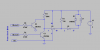
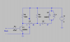
Now, I've used the blue portion of the circuit in my drawing (attached) successfully: I generate a 5v pulse every second from an arduino. The solenoid actuates and everyone's happy.
**broken link removed**

**broken link removed**

The 1.3v from the quartz movement isn't enough to trigger the 2803 though it seems, so I read up and decided I need a comparator to fire a pulse whenever there was a voltage from the quartz chip outputs. Don't have a comparator, but read that I could use an opamp as one... Constructed circuit B (red circuit) with no result. I did notice that I did get movement when I connected one of the quartz chip output to the same ground as the opamp though, but it was inverted. That is, the solenoid was on for most of the time, but briefly pulsed off every second. Ha, says I, maybe I can use the other op amp on the TL082 as an inverter (that should be possible I think?), but as I rewired it I noticed that the output of the second opamp was behaving the same the output of the first one - even though it had no inputs wired up. (circuit c - purple).

So that made me pause and wonder if it was something to do with the power to the TL082 that was making this behaviour. Was my circuit doing something funky to ground.

Anyway, at that point my rudimentary electronics knowledge was all used up, and I thought I'd better ask someone who knows something.. Ie you guys.

Any ideas for what's happening here, or what I _should_ be doing? Hope someone can give me a hand here!

Thanks
Sandy Noble
 
Last edited:
You probably don't need a comparator. if you do, TL082 is not a good part for this application. You can probably do this with an NPN transistor and a couple of resistors.
How much current does your solenoid require? If you don't know, then what is the resistance?
 
Thanks for your reply - I guessed the TL082 wasn't the best part for the job, but it was nearby so I thought I'd give it a shot. Of course I'd prefer to do without it if I could get away with it. Do you think I need the darlington pair? I only

The solenoid I'm using is a 6v, 3W one, it's internal resistance is 12.5 ohms (BLP | Process Control | Solenoids and Actuators | D Frame Solenoid | General Purpose, Push And Pull Action |44A-220-621-540).

I thought the comparator might be nice because it seems like it would take a lot of the "tuning" out of the circuit - make it a lot more tolerant of weird signals from the quartz timer. Part of that is because I don't really understand it's behaviour, part of it is because I would like a circuit that is quite general purpose and cobble-together-able so it can be made from a bigger range of parts. That's the ideal goal, but I'm happy to get something that works at the moment.

Thanks!
SN
 
Try this. Use an NPN to amplify the ~1.2V pulse from the clock circuit up to a voltage level which will switch the first ULN2803 input. Since you need a net inversion (output low while clock pulse high), use an extra stage of the ULN2803 as an inverter. The NPN stage inverts, so the net result is the solenoid being driven only when the clock pulse is high (+).

The NPN transistor used this way has a logic threshold of about 0.6V, which is just right for the low voltage pulse out of the clock chip.
 

Attachments

  • DF96a.png
    DF96a.png
    13.8 KB · Views: 554
The 1N4002 is redundant. Otherwise, I like it.:D

Old habits die hard. There are snubber diodes on all eight channels inside the ULN...
 
Hi Mike, thanks very much for the diagram - got it all wired up and not quite working... Not working at all actually, so I went back over my work and realised I've probably miscalculated the output voltage of the quartz chip - it's a lot more like 0.2v pulses measured on my voltmeter with peak hold. I had worked out the previous voltage by measuring the values from an input pin on the arduino and then multiplying by 5/1024... but I guess that wasn't as clever as I thought. I had tried using that method of reading because I thought I was misreading my voltmeter because of the constant fluctuations. Hm.

The output actually goes from zero, to -0.028v (ish) then up to 0.22v (ish) before going back to 0 for the rest of the second. I'm assuming this is some kind of capacitor charging/discharging cycle, and there is a little tin can on the pcb. I wonder if it might be worth changing this cap to increase the voltage of the pulse? I already tried changing the supply voltage to the quartz pcb and it sizzled and made a bad smell. Got a new one since then.

I don't really want to have to get any particularly esoteric parts to measure this beyond what I've got in my box already (hence the opamp hack earlier), but I'm assuming that a fix for this is more than just changing resistor values.

Roff, I did reply last night, but I guess my session must've timed out cos it never appeared! The solenoid is a 6v 3W one, resistance is 12.5 ohm.

Cheers guys!
 
I had an idea, but changed my mind. This forum doesn't allow deleting, which is what I would have done.
 
Last edited:
On the clock circuit; is this one one that used to run on a single 1.5V battery cell, that drove a small coil that steps a variable reluctance motor? If so, did you replace the motor coil with a load resistance of some type? How was the motor coil connected? Between two pins coming out of the epoxy blob? Is either of those pins tied to either the plus side of the battery, or to the minus side?

Here is a previous thread that dealt with using the pulses out of a wall clock chip...
I looked up a datasheet that showed a similar hookup. The chip generates a short positive pulse on each of the 2 lines, and they are 180 degrees out of phase. This means the both the high and the low levels have to be low impedance, so one output should give decent pulses without a pullup. This assumes that his chip is similar to the datasheet I found.
 
MikeML, that's exactly right, theres a epoxy blob with two lines going in (AA sized battery), and two lines coming out (to pads that had one end each of the copper wire that was round a little coil soldered to it. The coil was around a horseshoe shaped core with a tiny magnet and gear mounted near it's mouth). I didn't replace the coil with anything - I was pleased enough that I got a signal out of it at all. The output lines don't seem directly tied to the pos or neg- If I measure the voltage between the negative on the battery and one of the output lines then the swing is from 0v to 0.2v, whereas the voltage between both outputs swings between -0.02v and +0.2v.

I had read about the pos/neg polarity reversing driving of the stepper motor in the clocks, but wasn't sure if that was what I was seeing - since one of the pulses was so weak, and it also doesn't seem to be regular enough. It goes -0.02v, then straight to +0.2v every second, rather than every two seconds. It is certainly true that before I dismantled it, each tick used to turn the tiny gear 180 degrees, so it ran at 30rpm. To add complications, I don't actually need a pulse every second, I really just want a pulse every minute. I was going to put a dual decade counter inbetween the clock output and the darlington pair to tot up the 60s. I was leaving that bit til I managed to get a per second count out, but maybe there's an easier way to get 30 pulses per minute out instead? Doesn't really make any difference either way. I am also aware that these little low-power circuit are very finely tuned to drive the hardware they are usually attached to, and I've stripped that all away so I might be seeing artifacts of it behaving weirdly in this circumstance.

Thanks for looking up that other thread, that's very helpful indeed. I think I will probably add KenMoffats OR diode output stage to my clock to try and regularise it's output a bit. Ron I don't know what to say about my DMM, it's a fairly ordinary, cheap one.

My fall-back plan is to stick a magnet onto the end of the second hand and have it trigger a reed switch every minute! This idea of using a clock module as a driver was to make the circuit simple... but perhaps I am making a rod for my own back, and a dedicated ic (real time clock?) might be make it much easier.
 
Last edited:
Ok, the two complementary outputs are pulsed. The coil is driven only a few ms out of each second, otherwise the AA battery would be dead in a day, instead of a year...

The reason you see only +0.2V on the output is because the pulse is actually ~1V peak, but is only on for a few ms. You DMM is displaying the "average" or "true RMS" value, depending on how much you paid for the meter.

Disconnect the little coil, and try again. One output should pulse once per two seconds. The pulse duration might be not be long enough to pulse your big solenoid. If not, you might have to add a one-shot pulse stretcher (555) to allow your big solenoid to go "clunk". If you want your solenoid to pulse once per second, then you will have to add the "OR" gate shown in the other thread.
 
Last edited:
The coil is actually already disconnected, I meant to say that I didn't replace it with anything - when I desoldered it. My meter isn't clever enough to do true RMS I don't think, it's not an especially good one. I expect this is why the sampling from the arduino pin give me a higher figure.
 
Ok, the two complementary outputs are pulsed. The coil is driven only a few ms out of each second, otherwise the AA battery would be dead in a day, instead of a year...

The reason you see only +0.2V on the output is because the pulse is actually ~1V peak, but is only on for a few ms. You DMM is displaying the "average" or "true RMS" value, depending on how much you paid for the meter.

Disconnect the little coil, and try again. One output should pulse once per two seconds. The pulse duration might be not be long enough to pulse your big solenoid. If not, you might have to add a one-shot pulse stretcher (555) to allow your big solenoid to go "clunk". If you want your solenoid to pulse once per second, then you will have to add the "OR" gate shown in the other thread.
A diode OR gate is going to leave very little voltage to drive the base of an NPN, especially as the battery reaches the end of its life. A 2-transistor NOR would be better, IMHO.
An oscilloscope would do wonders to resolve the question about pulse amplitude. Euphy says his DMM has peak hold, but I wonder what the minimum pulse width is for this function to be accurate. The Fluke 87V (≈US $400) will capture pulses as short as 250uS. To do this, I would think they would need either a precision rectifier, or a relatively fast A/D. I believe that cheap DMMs use a dual-slope A/D, which is very slow. Peak hold could be as simple as holding the highest reading acquired over several conversion cycles. Since the dual slope A/D integrates, it will not accurately capture short pulses.
 
Here is another hack which implements a NOR gate by using two NPNs (remember RTL?). This should work except that it doesn't address the pulse stretching issue. Try it, and see if your big solenoid twitches. If it does, then all we need to do is lengthen the pulse by adding a circuit.

This would sure be easy if you had an oscilloscope... ;)
 

Attachments

  • DF96b.png
    DF96b.png
    17 KB · Views: 320
Here is another hack which implements a NOR gate by using two NPNs (remember RTL?). This should work except that it doesn't address the pulse stretching issue. Try it, and see if your big solenoid twitches. If it does, then all we need to do is lengthen the pulse by adding a circuit.

This would sure be easy if you had an oscilloscope... ;)
That's what I suggested. However, if one transistor didn't twitch the solenoid, neither will two of them.
 
Ha ha, oscilloscope is on my christmas list obviously! No dice with that circuit either. I've been using a supply voltage of about 4.5v. If I turn it up to 5.3 then the solenoid activates enough to hold the plunger in, but continuously, although I suppose it is possible that it has an off pulse that is too short to make a difference I had been keeping the voltage low while I was experimenting so I didn't blow something up.

Here's the output I get when monitoring the clock module with an arduino (just set to loop getting the value from the analog pin and then log it when it changes):
milliseconds are on the left, value is one the right. The value goes from 0 to 1024: 0 to ~5v. My supply voltage to the measuring arduino is 5.08v on my DMM, and that measures 1024 on the pin. If that makes sense.

The list below is with both two output pins plugged into the gnd and analog input on the arduino.

millis - value from pin
27836 0
28827 273
28836 274
28848 273
28860 0
29827 12
29836 0
30827 273
30838 274
30849 273
30860 0
31826 12

See it ticks every second here, one big long one (1.3v), one very small one (0.05v). That's more like it.

If I plug the clock negative supply into the ground instead of one of the pins I get
millis - value from pin
2923 0
4883 275
4892 274
4902 275
4915 274
4923 0
6884 274
6892 275
6902 274
6913 275

which is one 1.3v pulse every two seconds, lasting about 30ms and that is the same, regardless of which of the two output lines is being monitored - there is no positive or negative. Now, I'm quite happy to get a pulse every 2 seconds instead, so I'm going to work on that basis.

If I monitor the completed circuit that you (Mike) previously gave me (with the one transistor only), then the base of the npn transistor measures a pulse of around 0.54v every 2 seconds, but the emitter of the transistor measures a ~0.46v ... with a drop to 0.02v every ~2000ms!! I think that's it! I'm writing this as I'm testing btw, if you are concerned by my narrative style. However I can't find a corresponding dip in the voltage on the output of the darlington pair - it stays high all along.

This is quite exciting!
 
Last edited:
The emitter of the transistor is at ground. If you're measuring with respect to ground, the emitter should always be at zero volts. What's up with that?
Doo you have the negative side of your 1.5V clock power battery connected to circuit ground?
 
Oops yes, of course I meant the collector! (minor details... ahem) Sorry. the emitter is at 0v.

The negative of the 1.5v clock module battery is connected to the ground of the rest of the circuit.
 
Last edited:
Status
Not open for further replies.

Latest threads

New Articles From Microcontroller Tips

Back
Top