Continue to Site

Welcome to our site!

Electro Tech is an online community (with over 170,000 members) who enjoy talking about and building electronic circuits, projects and gadgets. To participate you need to register. Registration is free. Click here to register now.

  • Welcome to our site! Electro Tech is an online community (with over 170,000 members) who enjoy talking about and building electronic circuits, projects and gadgets. To participate you need to register. Registration is free. Click here to register now.

using a Mosfet as a voltaje controlled resistor.

Status
Not open for further replies.

Mortalo

New Member
First of all...
How are all of you doing ?
I hope all of you are fine.

I'm writing this thread because i have a confusion about how to configure
a mosfet to behave like a resistor so i can control the current in a range from 4ma to 20ma.

This is what i understand...
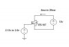
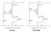
lets say that i have a voltaje source about 12v between drain and source, this is my vds. If i conect another voltaje source on the gate im going to have 0 ids as long as this voltaje is 0. BUT if i increase this voltaje to VT (vgs = VT) and continue increasing from this value(vgs > VT) the current between drain and source will increment too.

Fo this i used a BS107 that says on its "on characteristics" that its
vgs = 2.6v and its ID = 20ma.

So i said to myself that if for a vgs = 2.6v im going to have a current of 20ma i only need to find the vgs to have a current of 4ma. so i proceed this way.

ID = K(vgs - VT)^2
with
ID = 20ma
vgs = 2.6v
VT = 1.75

the constan "K" gave me a value of 2.781x10^-2

so with the same formula i looked for a vgs with ID = 4ma

vgs = sqrt(4x10^-3 / 2.7681x10^-2) + 1.75
vgs = 2.13 volts

so for a range of 4ma to 20ma im going to need a range of 2.13v to 2.6v on vgs.

What am i doing wrong ???

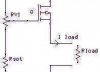
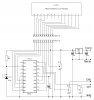
im going to post the circuit.

Thanks in advance
 

Attachments

  • circuit1.JPG
    circuit1.JPG
    7.4 KB · Views: 262
hi,
One way to get a controlled current source is by using a PMOSFET.

Choose the value of Rsense and RV1, such that the voltage drop across the Rsense is proportional to the current in the load resistor.

Rough example:
By setting the gate voltage using RV1 to turn on the FET and
say Rsense is 200R and Imax= 20mA then Vdp across Rsense = 4V.

Reducing the gate on gate voltage [wrt the +V] will reduce the current in Rsense until a balance is reached, it could be set for Imin = 4mA, so the Vdp across Rsense = 200R * .004 = 0.8V

The actual resistor values will depend upon which PMOSFET you choose.

This circuit is normally used as a Constant Current generator.

Do you follow OK.?
 
Last edited:
Hi Eric,
Your P-channel Mosfet is drawn upside down. I corrected it.
The schematic is fuzzy because you saved it as a fuzzy JPG file type that has losses instead of as a very clear GIF or PNG file type that has no losses.
 

Attachments

  • P-channel current source.PNG
    P-channel current source.PNG
    36.3 KB · Views: 496
Hi Eric,
Your P-channel Mosfet is drawn upside down. I corrected it.
The schematic is fuzzy because you saved it as a fuzzy JPG file type that has losses instead of as a very clear GIF or PNG file type that has no losses.


Woops,
Thats what happens when you load a symbol from the drawing library and forget to rotate it.:eek:

The screen snapshot I use only saves in jpg

Thanks.

EDIT:
You may find this link of interest, I am no musician...
https://www.electro-tech-online.com/threads/audio-filter-with-comparator.40268/
 
Last edited:
The corrected drawing of the current source.
 
Last edited:
I make a screen snapshot and open it and manipulate it with Microsoft Paint. Then I can save it as any file type I want.
 
When I make a screen snapshot I open it in Microsoft Paint which I use to manipulate it.
Then I can save it as any file type I want.
 
Last edited:
hi,
One way to get a controlled current source is by using a PMOSFET.

Choose the value of Rsense and RV1, such that the voltage drop across the Rsense is proportional to the current in the load resistor.

Rough example:
By setting the gate voltage using RV1 to turn on the FET and
say Rsense is 200R and Imax= 20mA then Vdp across Rsense = 4V.

Reducing the gate on gate voltage [wrt the +V] will reduce the current in Rsense until a balance is reached, it could be set for Imin = 4mA, so the Vdp across Rsense = 200R * .004 = 0.8V

The actual resistor values will depend upon which PMOSFET you choose.

This circuit is normally used as a Constant Current generator.

Do you follow OK.?


Thank you very much for your reply eric and audio guru.
So let me see if i get this straight.

You're saying that i need to put the mosfet on an "ON" condition by means of the voltaje drop on RSAT and RV1 and make sure that the IDmax = 20ma.
So reducing the voltaje on the gate ( voltaje drop on RSATand RV1), at some point i'm going to have an IDmin = 4ma.

Correct me if im wrong.

Thanks.
 
hi,
Assume you use a PMOS enhancement FET.
When the pot slider is at the top [on the drawing] the FET is not conducting so there is no voltage drop across the Rsense resistor.

If the pot is slowly turned so that the FET starts to conduct then the current thru the sense resistor will create a voltage drop across the Rsense.

This voltage drop will cause the current thru the Rsense and the FET to stablise. By choosing the value of Rsense and FET gate on voltage, values of 4mA thru 20mA can be achieved by adjusting the pot.

The Vsupply must be high enough to allow for the voltage drop across the Rsense, FET and Rload at 20mA.

A PNP transistor can be used in place of the FET.

For a Constant Current source, the gate voltage is derived from a fixed reference voltage. So as the load resistance varies the current in the load remains constant.

What are you using the current source for.?:)
 
Hi Eric,
The schematic is fuzzy because you saved it as a fuzzy JPG file type that has losses instead of as a very clear GIF or PNG file type that has no losses.

Maybe it is your monitor, the file looked fine on my end. MS Paint is crude at best for file manipulation. I use Photoshop, and all my files are saved as jpeg. This format gives good compression, offers vast array of colors, and you can control amount of loss. This is something GIF can never do. PNG is too large.

Look at my website, I host a large amount of jpeg photo's which I think look good. :)

Oops, went off topic. My apologies.

**broken link removed**
 
Last edited:
hi Mike,
I also choose jpg for its smaller size and it colour range.;)

With regards to fuzzy, as long as the drawing is readable I dont mind fuzzy.
[or the background grid dots]

I use the expressch freeware for circuit diagrams, if its a full size drawing with lots of detail I convert to pdf.

If its small drawing just to explain to the OP a particular point, I use screenhunter freeware to get a jpg clip

Regards

I'll visit your site.:)

PS: Just a quick look, I didnt realise it was about earth science.!
One of my subjects of interest.
 
Last edited:
hi Mike,
I also choose jpg for its smaller size and it colour range.;)

You are mis-informed Eric, JPG is fine for photo's, but for diagrams like these it produces a MUCH larger file size, and much lower quality.

So use either GIF or PNG, both of which give 100% quality, and MUCH smaller file sizes.
 
You are mis-informed Eric, JPG is fine for photo's, but for diagrams like these it produces a MUCH larger file size, and much lower quality.

So use either GIF or PNG, both of which give 100% quality, and MUCH smaller file sizes.


Hi Nigel,
UIGC The jpg about 33% of the png.?

Clip from my PC's winexplore.

PS: New abbrv: UIGC 'unless I'm going crazy!'
 
Last edited:
You can't create a PNG from the JPG file, the file has already been ruined by the JPG encoding - you need to create it from the original perfect diagram - when GIF and PNG will be probably 1/6th of the JPG size.

hi,
Problem is my screen grabber only saves in jpg format.

As I have said, if it a detailed drawing, I go the pdf route and for general guidance docs jpg [screen grab].

I think compared to some of the drawing qualities I have seen submitted, mine arn't too bad.:)
 
Last edited:
What's wrong with the 'PrtSc' button?, why are you using a different program to do a screen dump? - I'm presuming you can't just save the image from your program, as you're using a non-registered version or something?.

All my programs are either registered or freeware, please dont infer I am using unregistered programs.

If I use PrtScrn I have to paste it into my PaintShop Pro, clip it and save the clip... It makes more sense to me to just to use ScreenHunter freeware and post the image.
Maybe the image the image is a little fuzzy, but its small in size.

I can't see what all the fuss is about. If I was posting huge bmp files I could understand the criticism.
 
Look closely at a schematic that was saved as a JPG file type:
1) Its straight lines have a haze beside them.
Its lines have many dots where the line changes direction and at intersections of lines.
3) There are coloured areas where there should be no colours.
A JPG file type has losses that cannot be corrected.

A GIF or PNG file type has none of these problems and is a very small file size.

Here is the first schematic in this thread. I zoomed in and increased the contrast a little.
Sure it is fuzzy.
 

Attachments

  • JPG file type.JPG
    JPG file type.JPG
    23.5 KB · Views: 143
Last edited:
All my programs are either registered or freeware, please dont infer I am using unregistered programs.

It seemed an obvious reason why you can't save the diagram properly, so why can't you?.

If I use PrtScrn I have to paste it into my PaintShop Pro, clip it and save the clip...

Giving you a high quality image and a small file size.

It makes more sense to me to just to use ScreenHunter freeware and post the image.

And does Screenhunter only save as JPG?, could explain why it's free I suppose?.

Maybe the image the image is a little fuzzy, but its small in size.

That's the problem, it's fuzzy, and it's NOT small, it's many times larger than it needs to be - so you're posting poor quality large files, instead of perfect quality small ones.

JPG is for photos, not diagrams.
 
For an example, here if the identical file as GIF (15K) and JPG (79K), it's for a dual channel LCD voltmeter using a 16F819.
 

Attachments

  • LC819_LCD.GIF
    LC819_LCD.GIF
    14.9 KB · Views: 154
  • LC819_LCD.JPG
    LC819_LCD.JPG
    78.8 KB · Views: 158
Status
Not open for further replies.

Latest threads

Back
Top