eblc1388
Active Member
Horray Eric!!!
Your GIF is perfectly clear. I zoomed in to 2000% and it is still perfectly clear.
My black and white JPG is not perfectly clear but it is much better than a fuzzy colour one.
It only works one way, i.e. zoom up. One should try zoom down a GIF to 25% of the original and see what is the result.
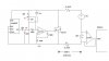
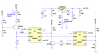
I hated it when people posting 2000x1600 GIF schematic diagram which one must scroll to see all the circuit. Though the author often posted a "size reduced" version, its image quality is most of the time really bad.
If one tries "size reduction" of the original large GIF image using an image processing software, sometimes the end results are bad. The thin connection wires disappeared. In this case a jpg schematic might perform better, when printed out.

")
")