Continue to Site

Welcome to our site!

Electro Tech is an online community (with over 170,000 members) who enjoy talking about and building electronic circuits, projects and gadgets. To participate you need to register. Registration is free. Click here to register now.

  • Welcome to our site! Electro Tech is an online community (with over 170,000 members) who enjoy talking about and building electronic circuits, projects and gadgets. To participate you need to register. Registration is free. Click here to register now.

which mosfet

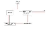
I need an advice on which mosfet will work for my project. I am running a 12V 3A load. I am using ESP8266 to turn it on/off. The system will change state up to 100.000 per year, maybe more in future, each state can be as short as 1 minute or as long as 30 minutes.

specs.:
- at least 12V, 3A
 

Attachments

  • mosfet.png
    mosfet.png
    11.5 KB · Views: 84
Describe type of loads, resistive, inductive, capacitive .....?

Need polarity reversal at load ?

Environmentals, T extremes.....

Any known HV transients at load ?


Regards, Dana.
 
Describe type of loads, resistive, inductive, capacitive .....?

Need polarity reversal at load ?

Environmentals, T extremes.....

Any known HV transients at load ?


Regards, Dana.
Resistive, its a simple heating resistor
no
room temperature
constant load 36W (12V 3A)
Would be great if it was rated for at least 1.000.000 cycles

Are you expecting the mosfet to switch the power that is powering the ESPmoduoe? How does the ESP module get power when the mosfet is off?
Esp module will use the mosfet to control the heating resistor, turning it on and off.


Thanks for the help
 
If this is a one-off project, you might look for one of these Xbox power supplies at the thrift store. These monsters supply 12 - 14 amps at 12 volts, and 1 amp at 5 volts.

But that's not all. The 12 volt supply is switched by a control line. When the control line is connected to +5 volts, the 12 volt supply is turned on. 3.3 volts may be sufficient but I've never tried it.

These supplies are often available for about five bucks at thrift stores.

SmartSelect_20240108_212445_Edge.jpg
 
How will i separate 12V and 5V with only 3 pins ?
MOSFETs are three terminal devices!

The negative (0V) of both supplies needs connecting - which it normally would be if the power source is 12V and you use a regulator to step that down to 5V.

The source goes to negative, gate to MCU output and drain to load negative, with load positive connected to +12V.

Something like this, but with your load in place of the relay coil:
(The IRF530 is not really suitable for 3V gate drive though - the FDP5800 is).

tE0uu.png
Thank you. It's my first time using mosfets, i think i am confused with the ground pin from the time where i was trying to use 3 pin relay and have control and power to relay supplied from separate sources - control from esp, power from step down. If i understand that correctly, i could do that also with the 3 pin relay then ? Connect 5V from step down to 5V pin, connect control pin from esp to control pin and both grounds from esp and step to G pin on relay ? I dont know why i thought i shouldnt do that
Isn't the ESP 3.3V only?

Mike.
P.S. I recently had to switch 12V (positive - not ground) using a P MOSFET. Here is the thread if interested.
GPIO's can only supply 3.3V, but they are 5V tolerant, meaning if you use 5V on board and drain through GPIO pin, u effectively have 5V. There has been lots of debate about that online so i was at first a little hesitant to try it
 
GPIO's can only supply 3.3V, but they are 5V tolerant, meaning if you use 5V on board and drain through GPIO pin, u effectively have 5V. There has been lots of debate about that online so i was at first a little hesitant to try it
But, to drive a MOSFET requires the pin to be output. Are you saying have a resistor (from gate) to 5V and switch the output low to turn the MOSFET off?

Mike.
 

Latest threads

New Articles From Microcontroller Tips

Back
Top