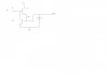
I have an old motorcycle from the early 70s with a 6V electrical system and no regulator -- as engine RPM rises, so does the alternator's output voltage. I would like to add a 6.8V, 50W zener diode shorted directly to ground, after the rectifier output, to keep the alternator from overcharging the battery.
I understand this is the same principal used in modern motorcycle regulators, but wanted a sanity check on the actual implementation. I found a NTE5247A zener which can be bolted to the frame, which would act as a very large heatsink.
Thoughts?

I understand this is the same principal used in modern motorcycle regulators, but wanted a sanity check on the actual implementation. I found a NTE5247A zener which can be bolted to the frame, which would act as a very large heatsink.
Thoughts?