hi,
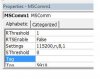
The factory default is 115,200 baud, so change the VB program to '115200,n,8,1'
Then check that you have a good connection using the $$$ and get the CMD reply...
I assume you have not changed the bit switch settings for the baud rate..????
Look at the image in post #40

")