Continue to Site

Welcome to our site!

Electro Tech is an online community (with over 170,000 members) who enjoy talking about and building electronic circuits, projects and gadgets. To participate you need to register. Registration is free. Click here to register now.

  • Welcome to our site! Electro Tech is an online community (with over 170,000 members) who enjoy talking about and building electronic circuits, projects and gadgets. To participate you need to register. Registration is free. Click here to register now.

Bi-Directional RS232 problem?.

Nigel Goodwin

Super Moderator
Most Helpful Member
OK, we're trying to reverse engineer an expensive lead, to see if we can make a cheaper version. The lead consists of a (fully moulded) FTDI USB plug, which goes to a 'Y' shaped moulded plastic junction 'box', then two leads out to four pin mil. spec. plugs. One of the plugs is male, one is female, and connects to a logger and an optional external battery pack. So you unplug the external battery pack, plug it in to the relevant lead, and then connect the other plug to the logger. The two plugs are simply wired A to A, B to B, etc.

OK, so C is ground, D is presumably power from the battery (but I don't have an external battery pack to test), A is RTS, and B is bi-directional serial data on one pin.

If you plug just the USB plug in, with a terminal program it will echo any keys pressed back to the terminal program.

Without the logger plugged in, pin B is normally high, as soon as the logger is plugged in, it's pulled down low.

It's all run via a custom PC program, and can download all the settings and data from the logger, and upload new settings etc.

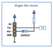
So has anyone got any suggestions as how to make the input/output as an FTDI chip work over a single pin? - bearing in mind I've no access to test anything, other than from the USB plug itself, and the two mil. spec. connectors. The lead is far too expensive to destroy, which is what I'd like to do, to examine it more closely.

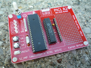
I've built a 'break out' board, so I can take scope readings etc. and disconnect any of the lines I wish, and I did try adding a schottky diode in the serial connection, but either way round it stops communication taking place.

IMG_1557[1].JPG
 
What's the data waveform & voltage range like on the data line, with the lead connected?

Idling high while disconnected but being held low while connected is definitely weird!
 
With a compliant RS-232 interface there is no way to implement a legitimate bi-directional data line. The "cheating" way to do it is with an open collector transceiver. The pullup to a voltage level greater than +3V is a compliant RS-232 level. The active pull down to "near ground" is not compliant but may work in many circumstances. To be compliant it would have to be at a voltage that is less than -3V.
 
Sounds like a typical "collision" bus communication design. This is very similar to the CI-V bus used in Icom radios (Amateur Radio). Multiple devices can communicate at any time, but each device has to check for "collisions" before transmitting. Once transmitting, a specific device has "control" until they are finished transmitting. On receive, all devices see the same data, and the protocol determines which device will act on the received data.
This type of communication bus usually has a small pull-up on each device, and input (receive) is high impedance. To transmit, they all use some form of open collector to draw the voltage down to initiate the data flow. Transmit should not start unless the data line is high for a determines number of "bits" or milliseconds.
The protocol has to be able to determine what to do when there is a collision if one device happens to transmit at the same time as another (can happen occasionally).
All this is also similar to thin wire Ethernet (RG58), often called 10Base2

Hint: Look for classic CI-V interface designs, there were many that interfaced MAX232 chips to the Icom CI-V bus.
 
With a compliant RS-232 interface there is no way to implement a legitimate bi-directional data line. The "cheating" way to do it is with an open collector transceiver. The pullup to a voltage level greater than +3V is a compliant RS-232 level. The active pull down to "near ground" is not compliant but may work in many circumstances. To be compliant it would have to be at a voltage that is less than -3V.
It's RS232 type, with TTL logic, as almost all serial is these days - so is effectively inverted.
 
What's the data waveform & voltage range like on the data line, with the lead connected?

Idling high while disconnected but being held low while connected is definitely weird!
It's typical 9600 baud TTL serial, 0-3V or so, and the default voltage is high (about 3V) as it should be for TTL RS232. I've just double checked on an FTDI module here.

My 'problem' is how it's connected? - I can't just join TX and RX together on the FTDI chip, but it must be isolated in some way in the lead?.

The PC software initially sends two ESC characters (0x1B) and some CR/LF etc. and a bit of gobblegook at 19200 baud, then the same at 9600 baud, the logger then responds and sends what has been requested. If the logger isn't connected, it continues to send the same at 4800 baud, then at 115200 baud - if there's no reply, it then sends '.....PDAC' at 19200 baud, then again at 9600 baud.
 
I can't really remember the details, but maybe some ramblings will trigger an idea.....

In ancient history times, the company I worked at used what they called an SIO bus within a data collector. It was a single wire TTL serial bus, where only one device could talk at a time. It was driven from the micro's UART pins using a two transistor and a few resistors interface. Sorry, but the exact arrangement is lost in 40 years of fog but I recall the transistors were essentially in series between positive rail and ground, with Tx being connected to one, Rx to the other I can't recall if the bus idled high or low.

The interface to the host computer was the two-transistor arrangement connected to a MAX232 chip.

Maybe this can trigger some ideas.
 
Of course. The MARK level is the pulled up value or "high", while the SPACE level is the ground level or "low: I have an Icom radio that uses this method of communication, and it works reasonably well. On a compliant RS-232 interface the MARK level is anything less than -3 Volts, and the SPACE level is anything greater than +3 Volts.
 
My 'problem' is how it's connected? - I can't just join TX and RX together on the FTDI chip, but it must be isolated in some way in the lead?.

A pull-up resistor and an open-collector output to pull low from the TX line.

As other say, it's quite a common system - both Amateur radio gear and one of the automotive diagnostic bus types use that system that I know of (though the automotive one pulls up to around 12V).
 
Thanks all of you, particularly for the mention of 'Icom' as a quick google produced this.

civ.gif


Which gives me some ideas, I'll delve further when I'm back at work on Friday. However, this does invert the data both ways, so I'll have to double check the polarity. No problem with power of course, as the FTDI module provides that.
 
Not exactly sure what you're describing, Nigel. Are you trying to connect FTDI RX and TX signals to a single pin on another device? If so, here's what I did awhile back on a PIC project. The PIC serial was bit-banged half-duplex and the putSer() and getSer() functions changed the data direction of the serial pin as required.

Is this what you're lookin' for? Do you need to see PIC code examples?

Regards, Mike
 

Attachments

  • single pin serial.png
    single pin serial.png
    14.1 KB · Views: 89
  • PICL R2 #1.png
    PICL R2 #1.png
    1.2 MB · Views: 86
Here is another image of a dual serial to a single serial interface used in the older BasicAtom processors: (works with TTL levels). Ignore the RES(reset line).

Untitled-1 copy.jpg
 
The Icom interface is designed to work from "real" RS232, so bipolar voltages and all inverted from the TTL side interface.
Yes, I know, the device in question uses standard 5V TTL polarity, so is reversed already - in fact I've got an extra FTDI module (RX only) clipped onto the B connection monitoring the data.
 
Not exactly sure what you're describing, Nigel. Are you trying to connect FTDI RX and TX signals to a single pin on another device? If so, here's what I did awhile back on a PIC project. The PIC serial was bit-banged half-duplex and the putSer() and getSer() functions changed the data direction of the serial pin as required.

Is this what you're lookin' for? Do you need to see PIC code examples?

Regards, Mike

We're trying to reverse engineer a VERY expensive lead, for an existing logger, and existing PC software - so no code required, as it would be of no use. It provides two way serial communication to download data from the logger, and to upload settings, all on a common pin, and of course everything is 'secret', including the pin connections.

Our customer wants to know if we can make them a cheaper version - but obvious not 'that' cheap, as we like to make a good profit.

And thanks for the simpler circuit :D
 
Here is another image of a dual serial to a single serial interface used in the older BasicAtom processors: (works with TTL levels). Ignore the RES(reset line).

View attachment 142954
Nice, I feel embarrassed now that I was thinking of taking the Icom circuit above, and adding extra transistors to invert the the data :D

If I get time tomorrow at work, I'll wire an FTDI module like that, and see if it works :D
 

Latest threads

New Articles From Microcontroller Tips

Back
Top