Continue to Site

Welcome to our site!

Electro Tech is an online community (with over 170,000 members) who enjoy talking about and building electronic circuits, projects and gadgets. To participate you need to register. Registration is free. Click here to register now.

  • Welcome to our site! Electro Tech is an online community (with over 170,000 members) who enjoy talking about and building electronic circuits, projects and gadgets. To participate you need to register. Registration is free. Click here to register now.

urgent help needed for PS

Status
Not open for further replies.

burhanmz

Member
Can some one please check whether this power supply is correctly made up or not...
picture below
ps-jpg.14972


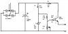
1.the rectifier are 4 diodes rated at 1Amp each, but i also have rectifier IC rated at 4Amps
2.the C1 charges up to max.72% thats 36volts
3. i am uncertain about the transistor.. i know the biasing is ok... but i actually need some current of more than 1Amp, so i set the collector current at 1.4Amps... would i get then would this power supply handle upto atleast 1.25Amps....
its sort of a project that i have to make, 0~12V regulated variable Power supply rated between 1amp to 3amp.

so plz.... help me and check (do all the necessary calculations) and tell me whether i should proceed to solder it all on a Vero board or not... or can some one suggest something else.. or better .... and i am not allowed to use more than 1 voltage regulator IC, so if u are suggesting me to use that then plz tell where and how will i supply the IC with negative voltage to make its rage from 0 to 12volts...
i have got LM350, LM317 and LM7805

plz help me as soon as u can....
 

Attachments

  • PS.JPG
    PS.JPG
    28.2 KB · Views: 433
and plz tell me where to put a fuse... before the rectifier bridge or at the end or some place else to protect my circuit from high current... 1.25 Amp fuse would do it...
and tell me whether i should place diode from emitter to base of transistor in forward bias position so as to protect transistor from if ever short circuited
 
burhanmz said:
and plz tell me where to put a fuse... before the rectifier bridge or at the end or some place else to protect my circuit from high current... 1.25 Amp fuse would do it...
and tell me whether i should place diode from emitter to base of transistor in forward bias position so as to protect transistor from if ever short circuited

hi,
I would recommend that you do not make this circuit.
There are many design flaws.

A LM317 will be able to supply 1amp, a heatsink maybe required depending upon the input voltage to the regulator,
giving a +12V output, variable down to about +1.5V

Does this help?

EDIT: added gif with numbers,,, the calculations do not make sense!:eek:
 
Last edited:
Sorry but this is an awfull circuit - dont build it!

Let us assume a specification of 0 to 12v, 1 amp max.

The circuit as drawn will only ever give a maximum of about 9.2 volts
zener (voltage 20 volts), divided by 2 (the two 5k resistors), minus the Vbe of the transistor (about 0.6 to 0.8 volts) = 9.2 volts.

If you try to take 1 amp from this circuit, the 25ohm 1 Watt resistor will drop 25 volts, and get very hot (W= VxI) it will dissipate 25 watts for a short while until it bursts into flames.

The output voltage will be variable, you can adjust it with the 5k variable resistor, but no way could it be described as regulated.
As you take current from the output, base current will flow in the transistor and the voltdrop through R3 and R4 will increase, the voltage at the base of the transistor will drop and so will the output voltage.

There is no feedback to give any regulation.

This circuit has NOTHING to commend it.

If you have an LM317, look here
**broken link removed**
download the datasheet and look at page 16 for a regulator circuit which can turn down to zero.

JimB
 
Last edited:
What if i remove the 25 ohm resistor and use a 10k ohm potential divider...., wht would happen then.... considering that i give a really good heat sink to transistor.

plz help me by giving some diagrams.... that LM350 page 16 circuit needs a -10volts... where do i get it a minus 10v... told u i'm allowed only to use one IC.
 
burhanmz said:
What if i remove the 25 ohm resistor and use a 10k ohm potential divider...., wht would happen then.... considering that i give a really good heat sink to transistor.

plz help me by giving some diagrams.... that LM350 page 16 circuit needs a -10volts... where do i get it a minus 10v... told u i'm allowed only to use one IC.

I have answered your PM.

The circuit will not give you the performance you require.

Which document is LM350 page 16?
 
In a PM, burhanmz wrote:
wht would happen if i removed the 25 ohm resistor from the collector terminal and left it as such

You would still have a circuit which was a pile of something unpleasant.

Try this circuit which I have attached.

JimB

PS Now that I have done your homework for you, please consider spending a little time to using correct English words instead text speak, you have a full size keyboard. plz uz it:eek:
 

Attachments

  • LM317 circuit.JPG
    LM317 circuit.JPG
    35.5 KB · Views: 199
I hate it when a thread just goes dead.
However, in a feedback comment burhanmz wrote:

thanks a billion trillion zillion times...by the way i'm just a freshmen, its my first year at electronics.....

JimB
 
hey dont worry... i still got many problems to discuss.
like, what can i use in place of a 5Watt 2.4V zener diode, because a 5watt at 2.4v is not available... 2.4 is available in 1watt and 1/2watt...
second that LM113 isn't available as well... the shopkeeper got heated at me and told me that there is a LM311 voltage regulator and no such thing as LM113....
third tell me if this circuit is any good...
and if yes... can u make it bear 1A atleast, say again using 2n3055...
and please be simple... dont give LM113
 

Attachments

  • PSU2.JPG
    PSU2.JPG
    17 KB · Views: 154
Your last attachment is not good. You cannot get much power through the 10k variable resistor.
 
In your last circuit:
1) Without a load, the power dissipation in the 200 ohm resistor is 2.7W and the power dissipation in the 13V zener is 1.5W and they will smoke and burn.
2) If the pot is set to maximum and the 2N3055 transistor has a typical current gain of 35 at 4A and a 4A load is applied, the output voltage is typically 11.5V and the power dissipation in the 2N3055 transistor is 94W and it will smoke and burn.
3) If the pot is set to half and a 2.5k ohm resistor is connected to the output then the voltage will be only 3.25V instead of half which is 6.5V. The voltage regulation is horrible and the load current is only 1.3mA.

Look in Google and you will have links to the datasheets for the LM311 comparator and the LM113 voltage reference.

EDIT: The transistor is a dinky little 2N3053. When the pot is set to max and there is a 50mA load then the transistor will smoke and burn.
 
Last edited:
burhanmz said:
what can i use in place of a 5Watt 2.4V zener diode,
You could try using four 1amp diodes in series. The zener is there to generate some -ve voltage from the main supply.

burhanmz said:
second that LM113 isn't available as well.
The LM113 is a voltage reference diode to generate a stable -ve reference from the -ve supply. You could try using two small signal silicon diodes (1N4148) in series.
This will not be as good as a proper reference diode but will work.

burhanmz said:
.. the shopkeeper got heated at me and told me that there is a LM311 voltage regulator and no such thing as LM113....
The man is an idiot.

burhanmz said:
third tell me if this circuit is any good...
It is no good, in some ways it is worse than your original circuit.

JimB
 
what is a reference diode. is there anything special about a reference diode like the one JimB mentioned above LM113...

how is it different from a normal working of diode...
 
JimB please add these two diagrams correctly...

1.can u change R1 to a variable resistance in 'current.jpg' so as to increase or decrease the current output.

2. [alternate] u said to use a zener diode of 2.4v in series with 4, 1A diodes, or just 4 diodes.

3. the 1k:eek:hm: resistor needs to be atleast 2watt rated, right.

4.what if i still can't find LM113..or LM313... something else i can use
 

Attachments

  • LM317 circuit.JPG
    LM317 circuit.JPG
    35.5 KB · Views: 123
  • current.JPG
    current.JPG
    9.3 KB · Views: 117
An ordinary diode changes its forward voltage when the temperature changes and when its current changes.
An LM113 voltage reference IC doesn't.

Digikey has some. They are very expensive.
 
burhanmz said:
JimB please add these two diagrams correctly...
Why? To achieve what?
One is a variable voltage supply, the other is a constant current generator.

burhanmz said:
1.can u change R1 to a variable resistance in 'current.jpg' so as to increase or decrease the current output.
Yes

burhanmz said:
2. [alternate] u said to use a zener diode of 2.4v in series with 4, 1A diodes, or just 4 diodes.
The meaning was:
"if you dont have a 2.4v zener, you could use 4off 1A diodes connected in series, instead of the zener"

burhanmz said:
3. the 1k:eek:hm: resistor needs to be atleast 2watt rated, right.
Yes

burhanmz said:
4.what if i still can't find LM113..or LM313... something else i can use
You could use 4 off 1amp diodes is series, but it wont work as well as an LM113.

Or alternatively, you could re-evaluate the design basis.
What is the purpose of this power supply?
Does it HAVE to go to 0v output?
What is the output current requirement?
Does it have a practical application, or is it just some academic exercise with arbitrarily imposed limits?
If so what are the limits?

JimB
 
What is the purpose of this power supply?
nothing particular.

Does it HAVE to go to 0v output?
yes.

What is the output current requirement?
at least 1.25 A

Does it have a practical application, or is it just some academic exercise with arbitrarily imposed limits?
If so what are the limits?
academic exercise, but it can be a future use for me. presently my lab sir is checking these power supplies with a load of 5:eek:hm: 10watt resistor, for 5 to 10 seconds... if the power supply fails... i get a good zero..(well not entirely zero)

i asked u if u could join those two circuits as as to increase the out put current. thats all..
and i sent sir Jimb another private message... if you would please answer it.
thanks.
 
Status
Not open for further replies.

Latest threads

New Articles From Microcontroller Tips

Back
Top