Continue to Site

Welcome to our site!

Electro Tech is an online community (with over 170,000 members) who enjoy talking about and building electronic circuits, projects and gadgets. To participate you need to register. Registration is free. Click here to register now.

  • Welcome to our site! Electro Tech is an online community (with over 170,000 members) who enjoy talking about and building electronic circuits, projects and gadgets. To participate you need to register. Registration is free. Click here to register now.

psu schematic needed

Status
Not open for further replies.

m3vuv

New Member
Hi all,i have a big psu with a big transfo+ 13 pass transistors on heatsinks,the control pcb is u/s so want to make a new one for it,i have a few lm723 ic's and a sg 3532,can anyone point me in the direction of a suitable schematic to use the sg 3532 chip,i would like it adjustable with cc and cv modes,thanks in advance.
 
He's not paying attention, just saw the "3532" number..

The SG3532 came out in the 70s, it's an ancient IC and no longer manufactured, from what I can see.

You would be better off using a newer part that you can get replacements for, if something fails.
 
You could try something like this, with the output stage modified for higher current; if it works with a 723, you could try dropping in the SG3532 & see if that works OK?


723s are readily available, so no problems with replacements if anything fails and you can always swap back from the 3523 if that does not work.

(No idea if that actually works OK or not, but does not look bad).
 
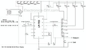
is that spam?,its nothing to do with the ic i mentioned!.heres a schematic,what needs changing to use the sg 3532 ic?
30V-10A-Variable-Bench-Power-Supply-circuit.jpg
 

Attachments

  • 30V-10A-Variable-Bench-Power-Supply-circuit.jpg
    30V-10A-Variable-Bench-Power-Supply-circuit.jpg
    54.3 KB · Views: 308
  • SG1532.PDF
    317.1 KB · Views: 269
The SG3532 was an improvement over the veritable uA723, and should work with some modifications.
For instance the SG3532 is nominally 2.5 volts, compared to the uA723’s 7.15 volts. The feedback resistors must change.

There are other parametric differences, you have to download both datasheets and make a list of those parameters.
 
I need to know what changes i need to make to the schematic i posted to make it work with the sg3525 ic
 

Attachments

  • lm723.pdf
    1,017.7 KB · Views: 250
  • SG3532J.pdf
    100.4 KB · Views: 277
would a tip-122 drive the bases of 13 2n3055 pass transistors,driven from pin 10 of the regulator ok?
Are you sure there are 13 'pass' transistors, it would be fairly usual to have 12, with the 13th being the driver that feeds them - the gain on 2N3055's is LOW!!!. There would then be a pre-driver feeding the single 2N3055 driver.

Is there any reason you're not just repairing the existing PCB?.
 
i an not repairing the old pcb as its in realy bad condition+ i want it variable like 0-30v/0-30amps if poss with cc+ cv modes one of the 2n3055 transistors maybe a driver,its not fully apart yet,it has lots of old coroded spade connectors so want to rebuild it using the transistors tranfro rectifier+ my sg 2532 also use 10 turn pots etc.,it looks like its been years in damp storage,its in a mucky terrible state.but could be a good base for a variable high power bench psu.,i am trying to decide on the available options i have using what i have ok.
 
Status
Not open for further replies.

New Articles From Microcontroller Tips

Back
Top