Continue to Site

Welcome to our site!

Electro Tech is an online community (with over 170,000 members) who enjoy talking about and building electronic circuits, projects and gadgets. To participate you need to register. Registration is free. Click here to register now.

  • Welcome to our site! Electro Tech is an online community (with over 170,000 members) who enjoy talking about and building electronic circuits, projects and gadgets. To participate you need to register. Registration is free. Click here to register now.

urban cart dash display (golf cart)

Status
Not open for further replies.
series resistor? which one you referring to?
r11(10k) and r15(3k) are a voltage divider?
I only wanted 6+volts feeding the regulateor circuit.
enlighten me as to what is wrong so I can correct.
Do you know ohms law? - and if not, what are you doing here?.

Apply ohms law to those resistors, and the current requirements of the linear regulator, it will be blindingly obvious what the issue is.

Basically it's on a similar level to you deciding to replace the wheels on your golf cart with house bricks, and thinking that's perfectly OK.
 
Apply ohms law to those resistors, and the current requirements of the linear regulator, it will be blindingly obvious what the issue is.
Exactly.

If the 5V circuit takes 100mA, its roughly equivalent to adding a 50 Ohm resistor across the lower half of that voltage divider. 10K + 50 Ohms divider means 1/200th of the input voltage...

Just use switched-mode regulator for the power supply, plus a separate voltage divider for the ADC monitoring.

(I gave you an example of a suitable PSU module in post #2...
https://www.mouser.co.uk/ProductDetail/TRACO-Power/TMR-2-4811WI?qs=ckJk83FOD0UmApu7/TRs8Q== )
 
I think if I use this in place of the https://www.digikey.com/en/products/detail/xp-power/SRH05S05/8021459 as per post #27 but voltage could be higher say 60v with fully charged lipo battery.

Well, you could look in the datasheet for the part, or you could read at least one of my prior posts...

Post #36
If you replace U2 with something like the XP Power SRH05S05 DC-DC converter that'll handle 9-72VIN

Post #39
The SRH05S05 is a DC-DC converter module. It puts out 5V, so you use it to replace the 78L05. That one handles any DC input voltage from 9V-72V.

It's about $8 US, in stock at digikey
 
MADE CHANGES AS SUGGESTED
 

Attachments

  • dash7.jpg
    dash7.jpg
    261 KB · Views: 180
MrDEB, you have outdone yourself this time! You have re-introduced EVERY ERROR addressed since your first post! MOSFETS, bypass caps, LCD connections. The SINGLE thing you got right in your post #56 sketch was the correct values for the ADC voltage divider resistors. (Post #56 sketch)

In your most recent sketch, why do you have R11 preceding the DC/DC converter input? Have you understood nothing about trying to power the voltage regulator via a voltage divider? The same comments apply to that resistor. What do you expect to accomplish with the zener D2? C1 & C2 should be located adjacent to the DC-DC coverter. ALL of the errors in the first paragraph still exist in your revised sketch*.


*sketch, because what you've drawn is so poorly drawn and laid out without proper symbols that calling it a schematic would be a far stretch.
 
edited schematic. I forgot to remove R11
D2 thinking as a safe guard against voltage error?
 

Attachments

  • dash8.jpg
    dash8.jpg
    261 KB · Views: 187
Your choice of an 18F2221 micro is odd, and it's lacking a feature you may want: a FVR (Fixed Voltage Reference). This gives you an accurate voltage reference to determine ADC voltage. Without an internal or external voltage reference, your ADC measurements use the PIC's 5 volt supply as the reference. Fortunately, the SRH05S05 DC-DC converter has a tight 1% tolerance on output voltage, so even if you do use +5v as the reference, you should get good results.

Looking at the availability of 18F micros, I'm pretty shocked at all the zero quantity availables I see in Octopart. I'd suggest using an 18F43k22 or 18F44k22 in a pdip package. More micro than you need, but there's availability (for now) at US suppliers. These micros feature a FVR.

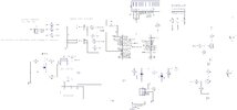
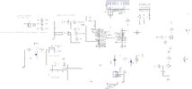
Here's a suggestion before everybody who is trying to help puts you on ignore. Instead of putting out an endless stream of sketches where you change one thing and ignore everything else up to this point, how about making a clean schematic with ALL of the changes? That means ALL CONNECTIONS shown, with proper symbols and all lines drawn, and no assumptions about what people will understand that you meant?
 
D2 thinking as a safe guard against voltage error?
What voltage error?
If the voltage is greater than the zener voltage of D2, how long do you expect D2 to last?

Make sure you have all the polarized caps installed the correct way.
 
D2 is on the output of the dc-dc converter.
I suggested adding one to the ADC_IN since it could see a large voltage at one point.
It may not be needed anymore now that the input is different.
 
Ahhh, didn't spot that, sorry. It doesn't help that some components haven't got a designator such as the zener on the ADC pin.

Mike.
How could you miss it? There are only 8+ versions of schematics where various features come and go without explanation.
 
Perhaps this will shortcut this painful tedious process. This schematic is based on 18F43k22 or 18F44k22 micros which have the desirable FVR and are in stock at US suppliers.

No guaranties, use at your own risk, yada, yada, yada. This schematic has been made using standard symbols, etc., as schematics should be made. Take note MrDeb - you should be good at it; you get enough practice.

Edit: fixed pullup connections at SW1 and SW2.
Edit: changed resistor values on P-channel MOSFET gates to better suit the 12 volt supply

Edit: I made a mess of the pullup resistors around SW1 and SW2. See the revised schematic in post #89.
Schematic_another deb folly_2022-04-14.png
 
Last edited:
the reason I am using a 18f2221 is I have a quanity on hand. On page 236 (18f2221) in the data sheet it mentions
CVR (control voltage reference) which I interpid as similar to FVR (page 289 data sheet 18f43k22). I have a quanity of these as well.
Are these two FVR and CVR basically the same?
I see "visitor" switched back to P channel. No part number?
I like the layout of the schematic thus will redraw my schematic.
the ADC_IN has suggested zener connected to R6 and R19. Yes my schematic is kinda convluted at best.
I like the use of Q2 mosfet for the backlight if needed but no switch to control Q2?
Will redraw and odmit the zener D2

It's done in your software, it's up to you how you want to activate it - there's plenty of spare I/O pins to add a separate switch if you want. You could also remove the contrast pot, and run that from the PIC via PWM, and set it via buttons on the PIC - in one of our commercial products I use a 1K resistor and a 10uF capacitor - and as it's only got three buttons, I access it via a 'secret' service menu :D

Switching the backlight could also be done direct from the PIC, no need for the FET, as long as you keep the backlight current below 30mA or so. The display we use in the product I mentioned above was upgraded by the manufacturer a couple of years ago, and the new version has far brighter backlights, so I was able to increase the value of the limiting resistor and lower the current.
 
Are these two FVR and CVR basically the same?

Not really. The CVR is primarily used as a reference for the comparators, not the ADC.
There's a way of wiring it to be able to use it as the ADC ref (by connecting CVREF to VREF+),
but because of the ADC VREF+ current requirements you'd have to add an opamp buffer in between the pins.

The FVR can be used for multiple things, like the ADC ref voltage

the ADC_IN has suggested zener connected to R6 and R19.
You can get rid of that zener now too.
At one point you were switching voltage dividers into the ADC_IN pin and it was possible to do an "oops", select the wrong setting, and over-voltage the uC pin by a LOT.

With the 10K/1K divider on the ADC_IN you should be ok with a CART_BATTERY voltage up to almost 58V.
 
As long as there's a large enough resistor feeding the pin from a large voltage then the pin protection diodes will "protect" it. You can even feed 230VAC into a pin via a suitable resistor.

Mike.
 
Status
Not open for further replies.

Latest threads

New Articles From Microcontroller Tips

Back
Top