Continue to Site

Welcome to our site!

Electro Tech is an online community (with over 170,000 members) who enjoy talking about and building electronic circuits, projects and gadgets. To participate you need to register. Registration is free. Click here to register now.

  • Welcome to our site! Electro Tech is an online community (with over 170,000 members) who enjoy talking about and building electronic circuits, projects and gadgets. To participate you need to register. Registration is free. Click here to register now.

urban cart dash display (golf cart)

Status
Not open for further replies.

MrDEB

Well-Known Member
have built an URBAN CART. Can't call it a golf cart since it was not manfactured by a "golf cart company" as defined by state law.
Enough of usless jargen. I built a two seat cart for my wife that is powered by a 1400 watt 48 volt motor. I call it "hot rod golf cart".
yes it is street legal here in town 25mph speed limit.
Want to design a dash display with a 4x20 lcd that displays MPH, odometer,battery condition and outside temp. Just carry me away.
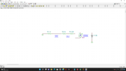
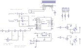
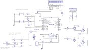
Using an 18f2221 pic , a temp sensor probe, a hall effect switch. Input the battery condition (48v Li-po4 battery) on a ADC input that is connected to a resistor ladder. see attached.
a 5v voltage regulator to power the pic
an RGB LED to visiulize battery condition (red= dead, green=good to go, blue=battery getting low)
An extra LED when exceeding 20mph. Easy to visiulize. could be a buzzer?
It has a backup buzzer already.
include a fuse array for lights, (brake, rear lights, headlights, motor )
the resistor array may need tsome adjustment since a 48v LIPO4 battery fully charged is 52-56volts.
any suggestions or additions?
 

Attachments

  • Screenshot (1).png
    Screenshot (1).png
    97.5 KB · Views: 235
One of these would be ideal for the electronic PSU; you don't have to worry about ground offsets as the 5V is totally isolated & you can connect the two grounds wherever is appropriate:

For the battery status, I'd suggest an offset reading "expanded scale" system.
Just feed the ADC voltage divider via a zener diode, eg. 33V or 39V

That means the readings don't start until close to the battery minimum voltage, so you get much better accuracy through the wanted range.

Battery voltage gauges do not normally read from zero, they only encompass the normal battery range plus a small amount; eg. see this as an example.

Offsetting the voltage the ADC "sees" as zero or near zero allow you to get the same effect, without wasting something like 1/2 or 2/3 of the ADC reading range.
 
An alternative (single chip) -

1648992457478.png


Of course the LCD and sensors external, but above interfaces (with associated API controls)
onchip. Fan controller onchip has PID capability.

If you need more than 4 ADC inputs just a click/config to add more to mux. Also if needed amps there
are OpAmps, Comparators, PGA onchip, all routable, just as the digital is internally routable. Resolution
of ADC eliminates fixes like zener scale expansion.

USB in case you want to do bootloader updates, Vref for A/D onboard, +/- .1%

IDE (PSOC Creator) and Compiler free. Very rare you have to write any drivers, each onchip
resource has a library of API f() calls. Substantial portions of designs, some all, can be done w/o
any coding, use of DMA and onchip logic and LUTs you can create state machines with.

Other onchip resources -

1648992618751.png


Regards, Dana.
 
Last edited:
one big problem the max input voltage per pic pin is 5volts.
Not a problem at all, and certainly not a big one - no different to an old analogue multimeter (where a typical one can only accept 0.09V), or a more modern digital one, which is going to be low, but 'might' be as high as 1.999V?.

Two resistors, job done - and while an expanded scale using a zener might sound like a good idea, the resolution of a ten bit ADC provides better resolution than you need for a simple battery voltage meter.
 
Or add a small value cap to the junction of the voltage divider/ADC input pin.
That will provide the internal Chold cap the charge it needs.
 
Chold? assume to retain input stability?
here is where I am in this design. Planning on software for voltage ADC amount.
will add a cap??
 

Attachments

  • DASH SCHEMATIC.jpg
    DASH SCHEMATIC.jpg
    300.2 KB · Views: 222
I'm not sure what you're trying to do with the ADC input, but you're going to release the magic smoke from the PIC. And probably some magic chunks as well.

You appear to be missing a ground connection to the switches as well.
 
You can probably get by w/o a OpAmp buffer since you are
not looking for high speed (I would gather in a golf cart),
hence do not need fast settling time. Unless source R is very
large, which could cause large offsets due to the 100 nA typ
input pin leakage. So if divider is 10K'ish types of R's then the
offset is only in the few mV range, even less in the single digit
K range. Note calculations are in datasheet that consider source
R considerations.

1649102652926.png


Modern processors usually buffer this onchip or have onchip OpAmps for that purpose
when dealing with fast systems or high impedances.


Regards, Dana.
 
Last edited:
Chold? assume to retain input stability?
If you look at the figure above, Chold is the internal sampling capacitor.
I'm not going to bother wasting my time as to why, but if you put a 0.1uF cap at the ADC_IN (RA0) pin that should help.

Once you fix the resistors values in that voltage divider, that is.
You might want to add a 5V zener at the ADC_IN pin too.

All a moot point since you'll have a hard time powering the 5V regulator with 40K of series resistance.
 
I'm not going to bother wasting my time as to why, but if you put a 0.1uF cap at the ADC_IN (RA0) pin that should help.
I always think of the 0.1µF capacitor as a "large battery" that can quickly charge the "tiny battery" (25pF) that is Chold.

Mike.
 
while laying in bed last night I realized I forgot to add a voltage divider for the rotary switch input.
 
here is revized schematic
hopefully zener is correct? and won't smoke.
added a cap at ADC_IN
 

Attachments

  • dash2.jpg
    dash2.jpg
    316.5 KB · Views: 224
I meant for you to add the 5V zener to protect the PIC input pin since you'll be putting more than 5V into it.

I think your voltage dividers/"simulated voltages" need some adjusting (or maybe I don't understand what you're trying to do). No matter what, I get WAY over 5V into ADC_IN.

The max voltage you can put into the 78L05 regulator is 30V, but with 30VIN it'll fry as soon as you try to pull any appreciable current out of it. The voltage divider will limit how much current you can get out of it the way it's arranged.
 
MrDEB, you should invest in Electrodoc Pro for Android and iPhone for less than five bucks. It includes calculators for calculating LED resistors, Ohm's Law, parallel and series resistors, Zener diodes and more - all those pesky details you don't want to learn anything about.

Electrodoc.jpg
 
I meant for you to add the 5V zener to protect the PIC input pin since you'll be putting more than 5V into it.

I think your voltage dividers/"simulated voltages" need some adjusting (or maybe I don't understand what you're trying to do). No matter what, I get WAY over 5V into ADC_IN.

The max voltage you can put into the 78L05 regulator is 30V, but with 30VIN it'll fry as soon as you try to pull any appreciable current out of it. The voltage divider will limit how much current you can get out of it the way it's arranged.

I couldn't make head nor tail of it either?, it doesn't help he's drawn half the circuit upside down.
 
Status
Not open for further replies.

Latest threads

Back
Top