Electro Tech is an online community (with over 170,000 members) who enjoy talking about and building electronic circuits, projects and gadgets. To participate you need to register. Registration is free. Click here to register now.
Welcome to our site! Electro Tech is an online community (with over 170,000 members) who enjoy talking about and building electronic circuits, projects and gadgets. To participate you need to register. Registration is free. Click here to register now.
well hopefully this is correct.
been dealing with a suspicious Lipo4 battery and/or charger as well as trying to find out why the cart motor dosen;t run now?
It ran before I put it away in the garage.
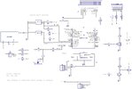
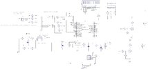
1. DC-DC converter should have input and output caps per the datasheet.
2. Voltage divider should have a 10:1 ratio to avoid too high of an input voltage into the PIC at max charge voltage. You had 100k/10k previously, which you changed to 9k/1k. Something in between that range will waste less power. Or use 100k/10k with CHOLD cap.
3. Why is the 7805 voltage regulator still shown?
4. LCD has no connection to +5V.
5. Why are you driving the N-channel MOSFETs with transistors?
6. PIC needs bypass caps.
What MOSFETs are you using? Are you planning on switching +12V to the lights and other loads or direct battery voltage?
You should have a suitably-rated MASTER switch to switch battery voltage to the 12v headlight DC-DC converter and the DC-DC converter used here, with the ADC voltage divider connection point downsteam of the master switch. Elsewise, you have a constant current drain and voltage on the PIC input pin when it's un-powered (that's a no-no).
You do realize the N-channel MOSFETs are a low-side switch, right? The switched loads will be connected to battery+, and the ground connection switched.
There may be more errors. This list is not all-inclusive.
Maybe you could post your best effort without known errors so people won't have to guess at what you may or may not know?
For example, Tumbleweed pointed out error 4, without any acknowledgement, and asked specifically what MOSFETs you're planning to use with no response.
I commented about error 2 previously, and explained why a 10:1 resistor ratio was desirable. Also ignored. No, actually changed on the schematic to values that would result in too have a voltage on the PIC pin.
Here I corrected hopefully ALL the errors
I have the mosfet labled and the 7805 regulator is gone. Changed resistor vales as suggested, added Vdd to LCD
Not that I ignored suggestions. I disambled a battery charger to see if it had 2-3 pin leds. It only has one 3 pin led and one two pin led.
I eanted to deermine if it had two GREEN leds. It is a chimeese charger w/ no description for using. Its only a 5A charger for Lipo4 48v batteries.
P-channel? N-channel? Typo'd part number that might be an obsolete P-channel? IRL9512 isn't a MOSFET. IRF9512 is an obsolete P-channel rated for 100v D-S and 2.5 amps output. Seems like an odd choice if that's the one you meant (since you show it switching 12V to the lights, not battery voltage). But as was ALREADY pointed out by Tumbleweed, you have the drain and source connections reversed.
And the same comment about not identifying MOSFETs should also apply to transistors don't you think?
If you look at the direction of the mosfet body diode in what you have drawn, the diode will always be forward biased so you won't be able to turn off the lights (at least not until the body diode blows up).
You're going to have a hard time using the ADC with those large values for R19 and R6. I'd drop them back down to 10K/1K and remove R3.
Add the suggested big honking ON/OFF switch to the whole thing if it doesn't have one already.
post#44 suggested
failed to include the On/OFF switch as well as an input for the hall effect switch.
I searched Digi-key and Mouser for mosfet.
Using octapart I found the IRL 95xx mosfets.
hold the presses.
While trying to run down WHY the motor wo't run I pulled out the schematic for the motor controller and AFTER I check out connections and voltages I may already have a 12v or 5v output.
will update tomorrow after I do more testing.
The 7805 would fry with an input voltage above 40V. You need a pre-regulator for that device, like a TIP41 or TIP3055.
I assume that you are using a 48VDC battery pack from a power jack or golf cart for this project - all the more power (sic) to you. I've not worked on those vehicles before, so I don't know their wiring layouts.
after yesterdays power outtage I hopefully can get out to the shop and track down Why the motor refuses to run.
In post #48 I listed the part as irl95xx
yes I need to research futher for a better mosfet.
post #53 looks like Jon C "visitor" is back? IMO
and no this project is not ending up in the trash.
well it is on/off rain/snow/icy rain etc but just had to get oout and do some measuring with DMM
here is a revised schematic and hopefully it passes mustard?
The 12v input s from the 12v converter from post#50 as is the keyswitch
the 7.5 volt input to 5v regulator circuit is for some recommended "headroom" for the 7805 regulator.
You cannot run a voltage regulator like that using a series resistor!
You MUST use a switching regulator (eg. a module) that can take the battery voltage directly.
It will only take between 3 - 6mA to drop the entire battery voltage across that 10K series resistor. With a linear regulator and a resistor-zener supply to that, the resisto must permanently take something more than the total circuit supply current.
eg. If that was 100mA, you would need something like a 300 Ohm 400 WATT resistor to feed the zener.........
series resistor? which one you referring to?
r11(10k) and r15(3k) are a voltage divider?
I only wanted 6+volts feeding the regulateor circuit.
enlighten me as to what is wrong so I can correct.
I looked at using a dc-dc converter but it would invalidate the ADC_IN battery condition.
This site uses cookies to help personalise content, tailor your experience and to keep you logged in if you register.
By continuing to use this site, you are consenting to our use of cookies.