Continue to Site

Welcome to our site!

Electro Tech is an online community (with over 170,000 members) who enjoy talking about and building electronic circuits, projects and gadgets. To participate you need to register. Registration is free. Click here to register now.

  • Welcome to our site! Electro Tech is an online community (with over 170,000 members) who enjoy talking about and building electronic circuits, projects and gadgets. To participate you need to register. Registration is free. Click here to register now.

urban cart dash display (golf cart)

Status
Not open for further replies.
oups yes I forgot to insert zener on the ADC_IN
The voltage dividor circuitry values were caculated using TINA simulation program.
circuit upside down??
circuit needs more work.
 
oups yes I forgot to insert zener on the ADC_IN
The voltage dividor circuitry values were caculated using TINA simulation program.

What's wrong with using ohms law?, or one of the many attenuator programs available on-line, it's not a job for a simulation program. But the entire divider network seems to make no sense?, never mind the values.

Also, what on earth is the 6.1v connection supposed to be?, if it's the power feed to the regulator feeding the PIC then it's completely crazy. What's with the three different battery voltages anyway?.

circuit upside down??

Yes, the drivers at the right hand side are all upside down - by convention you have ground at the bottom and HT (in this case +ve) at the top, it makes it confusing to have your high side switches at the bottom.

There are good reasons why circuits are drawn as they are, and doing it differently makes it far harder to follow.
 
I don't know what you've feed TINA, but:

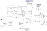
The three divider networks (R10/R12, R9/R13, and R11/R14) are all in parallel for a combined resistance (call it Rp) of Rp = 12.5K

That creates a main divider of R19 and Rp (10K + 12.5K) with a ratio = 12.5/(12.5+10) = 0.555
That's the VREG input (the node you've labeled "6.1V", which it isn't)
VREG_IN = CART_BATTERY x 0.555

Code:
CART_BATTERY    VREG_IN
48V             48V x 0.555 = 26.6V
36V             36V x 0.555 = 20.0V
24V             24V x 0.555 = 13.3V

Since the max voltage into the LM78L05 is 30V, you're ok there.

The problem is, the input to the regulator is through a 10K resistor/divider.
The divider limits the max current into the LM78L05, and you can't get more out of it than what goes into it:

Code:
CART_BATTERY    Divider Current
48V             48V/(12.5K+10K) = 2.1mA
36V             36V/(12.5K+10K) = 1.6mA
24V             24V/(12.5K+10K) = 1.1mA

That's not going to work.

Even if it did, if you put 26.6V into the LM78L05 it'll fry.
Let's say you want 100mA out of the regulator:
Code:
Pd = (VIN - VOUT) x IOUT
   = (26.6 - 5) x 100mA
   = 2.16W


A TO-92 package has something like a 150degC/W temp coefficient, so that's a rise of degC = 150 x 2.16 = 324 degC!!!!

I'm not even going to bother with the rest of it...
 
Last edited:
Working on a different approach instead of the voltage divider.
not sure what yet.
 
Working on a different approach instead of the voltage divider.
not sure what yet.

What's wrong with the simple approach?, two resistors, simple bit of maths, job done - a voltage divider - I've no idea what I'd try and call the mess you drew, but it wasn't a voltage divider.

Here you go - happy Easter for a weeks time :D

 
why not use divider on only 50v, then divider is simple,
1k:9k, = 5v on input at 50v battery
or 1k:10k to simplify.
then you can put selector switch seperate on pic inputs, and use software to calibrate trigger values for leds, since we prolly forgot that a 12v battery is dead at 8v and charged at 13-14v (not sure about a 48v battery)

also, 1k goes on the ground side since you are dropping 10k(45v) on the + side.

also i use a cheap 5$ "buck converter" for stepping down DC power supplies to 5v
 
Last edited:
also i use a cheap 5$ "buck converter" for stepping down DC power supplies to 5v

That's what I was going to recommend, but many of the the small 3-pin types don't accept 48V in.
There's the CUI V7805W ($12) and XP Power SRH05S05 ($8). They're both "linear regulator replacements".

That way the divider is only for the ADC input voltage.
 
well I think I got the ADC_IN corrected?
The mosfet section dosen't seem right?
Maybe us N channel instead?
 

Attachments

  • dash3.jpg
    dash3.jpg
    335.1 KB · Views: 189
You are trying to create a voltage divider. You haven't managed to get it right yet. Please search "voltage divider circuit" or simply look at the link Nigel posted. It's two resistors and THREE connections. Figure it out.

And please, use proper symbols for ground and voltage source connections and get rid non-standard ways of showing them you have used. Yes, people can decipher your weird scratchings. But they shouldn't have to search for obvious points and guess at your intent.
 
I used suggested values from post#26
1k, 9k, 50volts
Actually, your schematic show 1k and 10k, which is a better set of values.

Now, click Nigel's link on voltage dividers and compare what you've drawn to a voltage divider. What you've drawn is not correct. Two resistors, three connections.
 
You're not getting it. You can't power the 5V reg from a voltage divider and get any current out of it. The pic isn't going to need much, but things like the LCD backlight certainly will. Is the LCD VDD pin 2 connected to anything?

What voltage(s) can "CART BATTERY" be? How about you describe what all this is supposed to do instead of just plopping down a schematic for us to try and figure out?

The mosfet section dosen't seem right?
You got THAT right. What are the mosfets supposed to be doing? Switching a connection to GND? Switching a 12V input out to a pin?
 
I discovered my error. have corrected with attached as well as redid the mosfets
hopefully all is correct?
 

Attachments

  • DASH3.jpg
    DASH3.jpg
    331.6 KB · Views: 191
Do you understand the problem here?
The way you have it shown, the U2 5V regulator gets it's input through the 10K resistor.

Let's say you want 100mA out of the regulator. That means you need to have at least 100mA going into the regulator,
which means you'd have 100mA going through the 10K resistor.

According to Ohms law E = I x R, if we look at the voltage across the resistor that would mean:
E = 100mA x 10K = 100 x 10 = 1000V across the 10K resistor, which isn't going to happen. *TILT*

If you replace U2 with something like the XP Power SRH05S05 DC-DC converter that'll handle 9-72VIN,
so you can connect it's input directly to the CART_BATTERY. It's significantly larger and more expensive than the tiny little LM78L05, but that's the breaks if you want such a wide input range.

Then you can do whatever you need to with the ADC_IN voltage divider(s) and it doesn't effect the regulator.
 
Allow me to ask the obvious question:

The cart apparently has headlights (part of the point of this thread). Those headlights wouldn't operate directly from the cart voltage. Presumably they operate at 12 volts.

If that's true, then there's a source of 12 volt power that could be used to supply the PIC. A USB car adapter would be a nice solution. Or a 12v - 5v adapter could be hard-wired in.


Of course a DC-DC converter could be built on the PIC pcb. The design and layout using many different chips isn't that difficult, but does require a certain degree of attention to detail, which doesn't seem to be MrDEB's forte.
 
Looking at the XP Power SRH05S05 DC-DC converter that Tumbleweed suggested but instead of a 5v output go with a 6v or? seeing how the voltage regulator needs some headroom?
Yes there is an external 12v supply but only for the headlights and tail lights. If I used it to power the pic circuit we would have 12v-5v=7v wasted. Not sure how the power converter handles this.?
 
The SRH05S05 is a DC-DC converter module. It puts out 5V, so you use it to replace the 78L05. That one handles any DC input voltage from 9V-72V. It's a 3-terminal device and you wire it just like you would most 3-terminal linear regulators, but check the datasheet for recommended input/output caps.

A DC-DC converter doesn't waste power like a linear regulator does. You lose some power in the conversion, but you don't have the "12V-5V=7V wasted" problem. There's no point in explaining how it does that.

about using 12V...
If I used it to power the pic circuit we would have 12v-5v=7v wasted.
As opposed to the 48V-5V=43V wasted? Where do you think all the extra voltage goes with a linear regulator?
 
Last edited:
Now, moving on...

As Nigel pointed out back in post #34, your 2N2222 transistors short out the 12V when the transistors turns on. The collector needs to connect to the fet gate. It would also appear that your 'D' and 'S' labels are backwards.

What's the FET part number, and how much current do you need for the lights?
 
Status
Not open for further replies.

Latest threads

New Articles From Microcontroller Tips

Back
Top