dliqdzovuk
New Member
I have this transistor: https://www.electro-tech-online.com/custompdfs/2009/11/FG2FFGL60N100BNTD.pdf
I'm trying to use it to discharge a 350 V capacitor (capacitance isn't labeled, about the same as one you'd find in camera flash circuit). I have the positive terminal connected to the collector and right now, I just have the negative terminal connected to a resister and then to the emitter. The idea is to discharge the capacitor with a small voltage applied to the gate. However, while charging up the capacitor, the circuit shorts at a certain voltage (close to Vmax for the cap).
I've tested the transistor by putting the emitter to ground then putting the collector to a circuit that activates when applied to ground. I apply 4.5 V to the gate and the low-activated circuit turns on. This tells me that I either don't know how to read the product sheet or there's something I'm missing for when I need to discharge a capacitor. I've tried googling, but can't find anything on using high-voltage transistors as a switch for cap discharges. So could someone point me in the right direction?")
**broken link removed**
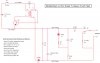
That's essentially the simplified version. In parallel with the capacitor is a charging circuit. I also simplified the triggering circuit to the switch. And keep in mind it is an IGBT, so I'm assuming I properly accounted for the bipolarity of the transistor when positioning the polar capacitor.
The desired result is just to have the current drain either through a thin wire filament, heating it up. Another possible result would be to rapidly discharge it through a wire loop to create a magnetic field. The point of the transistor is to have the action triggered by another circuit (e.g. serial port output from a computer, microcontroller output, certain logic conditions met, etc.) and thus avoid direct human interaction. This IGBT is just one that I happened to have access to. I don't have any experience with transistors, so if this one isn't suited for what I want to do, then I'm fine with buying something. However, if what I do have will work, I'd like to learn what I'm doing wrong.
I'm trying to use it to discharge a 350 V capacitor (capacitance isn't labeled, about the same as one you'd find in camera flash circuit). I have the positive terminal connected to the collector and right now, I just have the negative terminal connected to a resister and then to the emitter. The idea is to discharge the capacitor with a small voltage applied to the gate. However, while charging up the capacitor, the circuit shorts at a certain voltage (close to Vmax for the cap).
I've tested the transistor by putting the emitter to ground then putting the collector to a circuit that activates when applied to ground. I apply 4.5 V to the gate and the low-activated circuit turns on. This tells me that I either don't know how to read the product sheet or there's something I'm missing for when I need to discharge a capacitor. I've tried googling, but can't find anything on using high-voltage transistors as a switch for cap discharges. So could someone point me in the right direction?
**broken link removed**
That's essentially the simplified version. In parallel with the capacitor is a charging circuit. I also simplified the triggering circuit to the switch. And keep in mind it is an IGBT, so I'm assuming I properly accounted for the bipolarity of the transistor when positioning the polar capacitor.
The desired result is just to have the current drain either through a thin wire filament, heating it up. Another possible result would be to rapidly discharge it through a wire loop to create a magnetic field. The point of the transistor is to have the action triggered by another circuit (e.g. serial port output from a computer, microcontroller output, certain logic conditions met, etc.) and thus avoid direct human interaction. This IGBT is just one that I happened to have access to. I don't have any experience with transistors, so if this one isn't suited for what I want to do, then I'm fine with buying something. However, if what I do have will work, I'd like to learn what I'm doing wrong.
Last edited: