Continue to Site

Welcome to our site!

Electro Tech is an online community (with over 170,000 members) who enjoy talking about and building electronic circuits, projects and gadgets. To participate you need to register. Registration is free. Click here to register now.

  • Welcome to our site! Electro Tech is an online community (with over 170,000 members) who enjoy talking about and building electronic circuits, projects and gadgets. To participate you need to register. Registration is free. Click here to register now.

Capacitor question

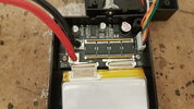
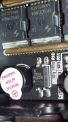
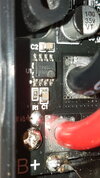
I would like to verify my understanding of super capacitors and i will give a practical example that i found online a few days ago. It was regarding a cheap spot welder with small lipo battery. It was said that the design is not good and it would be better to include a super capacitor to aid the small battery. So it made me think whether i understand how capacitors in combination with a battery actualy work. In the attached image there are 3 examples and i would kindly ask you to check if my understanding of it is correct. Thanks

spot welder.png
 
Adding a cap in parellel to the supply voltage is common, but depends on the circuits "thurstyness" for electricity.

What you intend is different. You want two redundent power sources?
 
Last edited:
The thing about capacitors is that both the charging cycle and the discharge cycle are exponential. They are NOT linear.
There are two conclusions you can draw from this bit of information:
  1. You can NEVER charge the capacitor to be equal to the battery voltage. It can get arbitrarily close in a finite amount of time but will take an infinite amount of time to be equal to the battery voltage.
  2. You can NEVER discharge a capacitor all the way to zero voltage in a finite amount of time. It can however get small enough that it is difficult to measure.
It is legitimate to have different resistors that control the actual charging and discharging times of the capacitor. If you are interested in pursuing this, I can show you the equations for charging and discharging a capacitor with different resistors.
 
I would expect some sort of current limiter to charge the supercapacitor, but then the limiter is bypassed when the supercapacitor is nearly fully charged. Depending on the application, the limiter could be a resistor with a switch that is manually operated when the capacitor is near enough to the battery voltage.
 
There are also different types of supercapacitor - some have quite high internal resistance and are not suitable for pulse circuits; some can be wrecked by high currents.

Others are designed for pulse applications - and there are general types inbetween.

Only use high current pulse rated ones in an application such as you show.

A couple of examples of higher current rated parts:

 
Ok, the second example where capacitor is connected directly to a battery with no resistor. Do this statements hold true ?

1) The first time we connect a capacitor to a battery we will get a spark and stress both battery and capacitor
2) Everytime the spot welder turns on, both capacitor and battery will supply as much as they can to the spot welder
3) When that happens, the capacitor will get empty and in effect again stress the battery because it will charge it super fast with no resistor
1) likely to be true, but I would say that the battery is likely to suffer more than the capacitor.
2) sort of true
3) not true

It's all a bit complicated, because the amount of power that the spot welder takes will depend on how much the voltage dips and for how long it dips when the weld happens. The amount that the voltage dips depends on the characteristics of the battery and the capacitor.

A capacitor that is connected to a circuit will reduce the amount that the voltage dips, so that that will reduce the peak current taken from the battery, and make the welder produce more power.

The capacitor will not become completely discharged, because the voltage will stay above zero, so the charging up of the capacitor after the weld will be less severe than connecting a completely discharged capacitor.

With a capacitor connected, the overall charge taken from the battery will probably increase, because the welder most likely takes more power if the voltage dips less and the capacitor has to be charged back up after the weld.

There are a lot of factors that come into this. An important one is how the welder behaves when the voltage dips. It may take less power (and make a worse weld) or it could take more power and stress the battery more, or something in between.

Another important factor is the internal resistance of the battery, so how much it dips for a certain current. The actual capacity of the battery isn't so important because the weld and the capacitor charging is too short to take a significant fraction of the battery capacity.

The capacitance and internal resistance of the capacitor is important. The internal resistance will control how much it helps the voltage dip, and the capacitance will define how long it can last for.

I was recently looking at a 12 V system where a battery was supplied from a power supply, and a motor would take about 500 A when starting. The battery and the power supply each had internal resistances of about 20 mOhm, so the voltage would dip by about 5 V, with about 250 A coming from the power supply and 250 A coming from the battery.

Of course, the voltage drop did reduce the peak current to the motor.

A supercapacitor of 500 F and about 5 mOhm would take a lot of the peak current, because it's resistance was lower than the battery or the power supply. That reduced the voltage dip and the currents taken from the battery and the power supply. At 500 F, the capacitor voltage would reduce at a rate of about 1 V/s when the motor ran, but the start-up was only 20 ms or so, and that didn't matter.
 
Thank you for a great answer sir !

So in short, if i want more amps, super cap in parallel with no resistor will help. If i want to protect the battery and cap, i should add a resistor (and make sure caps have enough capacity to do the welds themselves)

This got me thinking. Lets say the battery is the limiting factor in this case and not the spot welder. Meaning that the welder will happily take both cap and battery amps, maxing both. But if i had enough capacity in super capacitors, that welder couldn't take it all, then i would probably reduce the stress on the battery.

Let's say 1 weld takes 30 joules and my caps hold 120 joules. Then caps will always have juice in them and battery will recharge them between welds or when i prepare the nickel strip. Now battery will recharge the caps very fast with no resistor but surely this will still be less stress for the battery than the welding itself ?
 
The caps never discharge fully and only partially when across the battery.
Adding a higher ESR supercap in parallel to the battery, does nothing.
I do not expect a small supercap to speed up welding.

The energy dissipated from a supercap depends on the voltage after the discharge, which could be limited by the battery ESR and load current.

Therefore I do not believe adding a supercap is any benefit.
It will be very stressful on the battery, so I would not allow it to discharge more than 50% SoC.

Both supercaps and batteries are modelled simply by series ESR*C = Tau values and path length inductance of the loop.

An 18650 cell is about 10kF 75 mohms.
 
Would anyone dare to speculate what would happen if instead of capacitors, we added 18650 cells in parallel with the small lipo ? Lipo is charged to 4.2V, and we added 1S10P or 1S20P in parallel to the lipo. The 18650 cells are 10A rated each.
 
Putting different chemistry cells in parallel is never a good idea as you can get one cell charging the other and you don't know what is going to happen.

Capacitors in parallel with cells are fine (once you deal with the initial connection) because the capacitors can be rated to a higher voltage than the cells.
 
Just add one, two or three more batteries in parallel to get what you need.
 
Sadly i have no lipos except the one that i got with this cheap welder. So only thing i can do is either add caps or add 18650 liion batteries in parallel.

I was wondering, do u think it might be an option to just desolder this lipo and instead just use standard 18650 10A liion cells ? I have tons and tons of them and could easily add like 20P. Thats 200A which is surely more than a tiny lipo can supply. But not sure about internal resistance of my 18650 cells vs that lipo
 
Each 1 Ah capacity from 3.8 to 3.0 V equals 4500 Farads. C= Ic*3600s/dV

The current limit will increase each ESR in parallel and the strongest battery will supply the most current according to I=dV/ESR.

So adding Li Ions in parallel will improve your performance as long as your welder components do not get too hot from continuous use. Preventing undercharge or overcharge will improve battery lifetime discharge total. Limiting battery V between 50% SoC and 4V CV will improve that significantly.
 
I got probably 100 or more 18650's thats why i asked. Many arent good enough to sell or use in serious projects, but are still good enough to use for things, as long as i am aware that they are dangerous so i always wear protection and store them in a place where they cant cause house fire.

I am asking all this because this spot welder is a toy - for now i only use it as a hobby, maybe weld like 10 batteries a year. Modifying is learning and fun. I only have to decide whether just put 18650 in parallel with existing lipo, or desolder lipo and use 18650.

I have another problem with this spot welder. I accidently plugged 12V instead of 5V into it and burned the charging chip. Thats not a problem since i use external charging circuit now. The problem is that now it appears there is a small short somewhere and battery is losing capacity by about 0.1V per day. That makes it a problem if i suddenly decide after 3 months that i wanna use that device. So 1 option would be to physicaly unplug the battery when i am not using it, though that will take some work since its all soldered now. Option 2, but i am not sure about this one, would be to just desolder the charging chip with 6 legs. The only thing i am afraid is that it somehow still controls whether the battery is connected to the welder itself - meaning i am afraid that if i desolder the burned chip it will stop working. I will take some pictures though it wont be possible to read the model of the chip since its burned.
 
I added some photos of the mini spot welder. Mainly i am interested in this:

1) Can i safely desolder the charging chip, it's 8 legged chip thats burned, code reads TP405* B320*, thats all i can read since it's burned. What im mainly interested is if spot welder will still operate (ofcourse i will use separate external charging). Im suspecting this chip is at fault for battery losing about 0.1V per day

2) Mosfets controlling the welding. Will they be able to handle more current if i add parallel batteries. I plan to test it slowly and add cooling on top of them. But heat is only part of the equation regarding the board, other components, etc. Codes on chip read HYG011N04 A4AECLS1B
 

Attachments

  • 20240710_185229.jpg
    20240710_185229.jpg
    3.3 MB · Views: 86
  • 20240710_185234.jpg
    20240710_185234.jpg
    3.5 MB · Views: 86
  • 20240710_185329.jpg
    20240710_185329.jpg
    2 MB · Views: 81
  • 20240710_185455.jpg
    20240710_185455.jpg
    1.2 MB · Views: 87
  • 20240710_185503.jpg
    20240710_185503.jpg
    2.6 MB · Views: 95
  • 20240710_185526.jpg
    20240710_185526.jpg
    2.3 MB · Views: 84
  • 20240710_185646.jpg
    20240710_185646.jpg
    1.1 MB · Views: 78
  • 20240710_185722.jpg
    20240710_185722.jpg
    3.7 MB · Views: 109
  • 20240710_185726.jpg
    20240710_185726.jpg
    3.5 MB · Views: 87

Latest threads

New Articles From Microcontroller Tips

Back
Top