Continue to Site

Welcome to our site!

Electro Tech is an online community (with over 170,000 members) who enjoy talking about and building electronic circuits, projects and gadgets. To participate you need to register. Registration is free. Click here to register now.

  • Welcome to our site! Electro Tech is an online community (with over 170,000 members) who enjoy talking about and building electronic circuits, projects and gadgets. To participate you need to register. Registration is free. Click here to register now.

Transformer outputs?

Status
Not open for further replies.

bigal_scorpio

Active Member
Hi to all,

I thought that this was a simple thing but after reading up on the subject I am now confused.

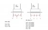
I have a transformer (240v primary) with 10-0-10 outputs and need all the current I can get from it! The question is can I simply join the two 10v outputs and get double the current or will this create problems with phases. I know it should be possible if the transformer has four wires (two pairs of separate windings) but as mine has only the two 10v and a single 0v center tap.

Can anyone clear this up for me so I don't end up killing the transformer (or me) hehehe.

Thanks for reading this................Al
 
It sounds like you have a 20V center tapped transformer. The current of an transformer is based on the size of wire used in the windings. Voltage across the 10-10 will give 20 volts and from each of the 10 to 0 will give 10 volts.

Check to see if the Amps are listed on the case or tag.
 
Post a video of you connecting the out-of-phase 10V wires together so we can see the explosion, huge fire or plenty of smoke. Just kidding, don't do it!
 
Do you want an AC output or are you converting it to DC?
 
Do you want an AC output or are you converting it to DC?

Hi Guys and thanks for the answers.

As to the question from crutschow, I will be rectifying the output as I intend to put it through a MosFet and use PWM to control it.

If I can't use the full current of the two 10v outputs I will have to find another transformer, but such is life, well electronics anyway. It seems that you can never have ALL the parts in your junkbox even for the simplest of projects!

Regards.............Al
 
Yeah, that won't increase the current, just the voltage. It should have the current rating stamped on it somewhere. That's what you get.
 
Yeah, that won't increase the current, just the voltage. It should have the current rating stamped on it somewhere. That's what you get.

Hi,

I thought that to increase the voltage that I would just use the two 10vs and ignore the 0v that gives me 20v and seems ok with a current draw.

What I mean is using both the 10vs in parallel to double the current.

Al
 
If the transformer has two completely separate 10V windings then they can be connected in parallel if you connect the phase correctly.
But a center-tapped winding has opposite phase at its ends and if you connect the ends it is a dead short across the 20V winding.
 
If the transformer has two completely separate 10V windings then they can be connected in parallel if you connect the phase correctly.
But a center-tapped winding has opposite phase at its ends and if you connect the ends it is a dead short across the 20V winding.

Hi Audio Guru,

Well thats cleared up one point but is there some way I could do it electronically, is crutschows ad or dc question implying that it would make a difference if I rectified the 10v outputs and then connected them in some way?

Thanks.............Al
 
A full-wave-rectifier can be made with a center-tapped transformer and two rectifier diodes.
 
A full-wave-rectifier can be made with a center-tapped transformer and two rectifier diodes.

Hi again Ausio Guru,

That sounds ideal!

Do you mean 2 diodes on each output? Could you elucidate a little?

Thanks again...............Al :)
 
Hi again Ausio Guru,

That sounds ideal!

Do you mean 2 diodes on each output? Could you elucidate a little?

Thanks again...............Al :)

Hi Al,
You will not get an overall power increase using this method.:)
 
Hi Al,
You will not get an overall power increase using this method.:)

Hello Eric,

Doh! Back to the drawing board then, well back to searching for more transformers!

BTW I hope the snow has been kinder to you than us, we have been trapped on the street for days at a time here, and its snowed again today thank god it rained afterwards. ;)

All the best..........Al
 
Hello Eric,

Doh! Back to the drawing board then, well back to searching for more transformers!

BTW I hope the snow has been kinder to you than us, we have been trapped on the street for days at a time here, and its snowed again today thank god it rained afterwards. ;)

All the best..........Al

hi,
Weather has been very cold but not much snow.
How on the transformer is the centre tap brought to the outside, is it connected to a terminal.?
 
Last edited:
Hi again,

Just thought I'd mention that I was planning on making a foam cutter with the transformer.

I would have used one of the plentiful SMPS that I have lying about but I have never had much success using them on anything other than purely resistive loads and I figured that seeing as I am using PWM to control the output I am guessing that the SMPS would dislike that?

Any thoughts?

Regards............Al

I would have thought that a 'heated' foam cutter would be a resistive load.???
 
Last edited:
Further on the transformers outputs!

Hi again,

After opening the transformers casing I can see that the center tap seems to dissappear into the windings at BOTH ends! So in theory I may be able to cur it at the center and have two separate windings.

If I can would that mean I could parallel them up and actually get the extra current?

Regards.....Al

Thats what I was hoping you find.:)

Carefully cut the junction of the two wires at their tips. Leave the wires as long as possible.
Use an ohm meter to check their resistances, they will have low resistance, almost equal.
Also check with meter, after the cut, that both windings are not interconnected to each other, so that you have two isolated windings,,,lets know,

EDIT:

IF the windings pass this test, then plug in the transformer to the mains supply, measure the 'ac' voltage of the two windings
in order to ensure that they are the same voltage.

IF they are the same, connect the windings as shown here.
 

Attachments

  • Al_txr1.gif
    Al_txr1.gif
    6.9 KB · Views: 160
Last edited:
Hi Eric,

Here are the results, what do you think?

Edit:- they are both 11.1v exactly.

Regards.......Al
 

Attachments

  • Trannyout.JPG
    Trannyout.JPG
    20 KB · Views: 163
Last edited:
Hi again Eric,

On my transformer the two center pins seem to be crossed inside the windings so should I connect A to B and C to D to get the configuration in your drawing?

And by the way what do F and S stand for on the drawing?

Edit:-

Yes thats right, its working now so thanks to all! :)

Thanks...........Al
 
Last edited:
Status
Not open for further replies.

Latest threads

Back
Top