Continue to Site

Welcome to our site!

Electro Tech is an online community (with over 170,000 members) who enjoy talking about and building electronic circuits, projects and gadgets. To participate you need to register. Registration is free. Click here to register now.

  • Welcome to our site! Electro Tech is an online community (with over 170,000 members) who enjoy talking about and building electronic circuits, projects and gadgets. To participate you need to register. Registration is free. Click here to register now.

Thermistor and Comparator Circuit

Status
Not open for further replies.
hi Al.

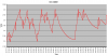
This data is from LTSpice. I have attempted to normalise the thermistor and associated circuit to 25C.

If you look at the Table data and Plot from LTS you will see that the switching point
ie: Vref does change with temperature on the half bridge circuit.

While it would in theory be possible to design the circuit as I half bridge using two matched NTC thermistors I would say in practice it would not be an option I would choose.

I would imagine trying to set up the hysteresis would be a task..:)

AAespPlot1.gifTable1.gif
 
Hi Eric, Im not exactly sure what you are trying to say there, but i do like your idea of making the circuit with two 100k thermistors just to make the simulation a lot simpler just so we can see the effects of two thermistors. The thermistors in practice dont actually have to be the same, but it's a good idea to start that way just to see how it will work out.

Now are you saying that the circuit doesnt look like it is working, or just that the hysteresis is going to be too hard to set?

If the latter, i think all we have to do is figure out the resistance of a single thermistor at two temperatures and take it from there.
I think after that we can even use the old equations to calculate VH and VL.
For example, using 100k thermistors (100k at the required temperature midrange), lets say at T1 it is 110k and at T2 it is 90k.
At T1 that means R14 and R4 (in your second circuit) are both 110k, and at T2 that means R14 and R4 are both 90k.
It doesnt matter that "Vref" changes, it only matters that the output switches state at T1 and T2.
If T1 was 10 degrees and T2 was 20 degrees and the output switches state at 10 and 20 degrees then we have it.
Remember his temperature spread isnt that wide either, only being something like 5 or 10 degrees, so the thermistors
dont even change that much (say about 10 percent).

Oh yeah one more little detail:
If we change the lower resistor to 100k that is 10 times what it was before, so we would have to change the hysteresis resistor
value to 10 times what it was before too, roughly.
ADDED: but then we have 2x the voltage change, so that feedback resistor would have to be 10 times what it was divided by 2,
which means 5 times what it was before. Since doing this will put the voltage trip points at roughly the same points as before,
one can ask if this is really making the sensitivity better. It might be better to run though an op amp first to get the better
sensitivity as that would make it closer to a bridge circuit with opposite arms being thermistors which was the basis for this
technique.
ADDED: It looks like the 'Adder' method is better though, as that allows increasing the sensitivity even more it seems (ie
two thermistors, three thermistors,...,ten thermistors) although it will take at least 5 more resistors. The interesting thing
though is that if one thermistor out of 10 goes out of tolerance, it affects the whole by only one-tenth of that instead of
the entire amount. Many thermistors however have good stability over time anyway.
 
Last edited:
Sorry for the delay in progress, I’ve been pretty busy. Anyway, I did the testing and it works…more or less. Here’s what I did:

I built up the circuit on a breadboard and connected the base of a PNP to the LM293 output through a 1KΩ resistor. I used the PNP to drive a 10Ω 10W power resistor that I placed directly under the thermistor. Essentially, it was the heater. I also placed a thermocouple style temperature probe directly adjacent to the thermistor. Then I stuck the breadboard into a Tupperware container and threw the whole mess into my freezer.

I monitored and recorded the voltage at the inverting input as it changed with temperature. I also checked the voltage at the non-inverting input as it changed with the comparator output. Lastly, I periodically checked the temperature with my second multimeter. The results of the testing are not totally expected but I think are explainable.

First things first, voltage at the non-inverting input (i.e. hysteresis band) had an upper set point of 2.62V and a lower set point of 2.29V. That’s pretty close to predictions and my desired 300 mV hysteresis band.

The voltage at the inverting input, as expected, varied with temperature but the unexpected part was that the voltage didn’t always get down to 2.29V or up to 2.62V before the comparator output changed state. Maybe this can be explained by voltage ripple from noise? I was recording the data through my multimeter’s RS232 output at a rate of 1 sample/sec so it’s conceivable that the voltage rippled above or below the set points without me actually seeing it. I was also running a clothes dryer about 8 feet away. Maybe that did it.

Another curious thing was that when the comparator output changed state the voltage at the non-inverting input changed as expected but what wasn’t expected was that the voltage at the inverting input changed too. You can see it on the graphs as a periodic vertical line of about 75 mV.

Since the upper resistor was set, the voltage at the inverting input should only change with changing temp or changing supply voltage. Since I know the temp didn’t change that fast the later must be the case. Maybe the .5A load through the power resistor changed the supply voltage? The power supply I was using is my home made bench power supply built on an LM317 that I had set as close to 5V as I could get it. In hindsight I should have been monitoring the supply voltage for fluctuations too,

The temp I measured wasn’t right where I expected but I question the accuracy and I also think the thermocouple reacted faster to the heat than the thermistor. The temp ranged anywhere between -3 to 10 C.

So I’d say it was a success. It didn’t function exactly as planned but it maintained temp pretty close to my expected range. Next I’m going to tweak some pots and see how much I can improve the range.

Attached are some pics of my test set up and also some graphs showing the voltage at the inverting input over the course of the test. About 1 hour total in between when I put the container in the freezer and I stopped the test.

Thoughts? Comments? Observations?

Thanks.
 

Attachments

  • 100_1256.jpg
    100_1256.jpg
    1.2 MB · Views: 227
  • 100_1251.jpg
    100_1251.jpg
    1.3 MB · Views: 225
  • 100_1252.jpg
    100_1252.jpg
    1.3 MB · Views: 209
  • 100_1250.jpg
    100_1250.jpg
    1.3 MB · Views: 213
  • Graph2.PNG
    Graph2.PNG
    23.4 KB · Views: 215
  • Graph1.PNG
    Graph1.PNG
    15.7 KB · Views: 212
hi vne,
A well documented and presented project test.:)

I would say that the 0.5A heater current could pull the +V supply line down so that the supply to the divider could change slightly. If its a problem you could use a Vref ic to stabilise the 'local' on board pbc voltage.

EDIT:
I dont see any onboard supply decoupling caps.?
 
Last edited:
hi vne,
A well documented and presented project test.:)

Thanks!

I would say that the 0.5A heater current could pull the +V supply line down so that the supply to the divider could change slightly. If its a problem you could use a Vref ic to stabilise the 'local' on board pbc voltage.

I'll look into the Vref IC.

EDIT:
I dont see any onboard supply decoupling caps.?

The only cap I had onboard is a 1uF cap between the inverting input and ground to try and smooth out any noise at the thermistor/415KΩ voltage divider. What would you suggest I add?
 
hi,
As the project is some distance away from the PSU and you are switching 0.5A into your heater a 220uF and 100nF on the project board would be a good idea.

Dont forget there is a voltage drop along that voltage rail cable which will cause a drop at the project board.

A point to note also, is that your 'measuring leads' will cause a change in the operating point also introduce some noise.
 
I second Eric's opinions about the test and documentation. Bravo!
 
Last edited:
Hi,


Oh yes, very nice documentation there! That makes this thread more interesting as we can see what's going on physically too now.

If nobody said this yet, then what you can do is look at the power supply line to see if it changes WITH the problem input terminal of the
comparator. If it changes the same way that the comparator input changes then it's a good bet that the power line is pulling that pin
with it as it changes due to the load. If not, you may just need more capacitance on the thermistor line close to the ic package.
It does look like oscillation, and that could be caused by the unwanted load-to-power-line-to-input-terminal feedback.

You could also look for changing thermal gradients, which occur if there is a breeze going past the thermistor,
even a small breeze that you can not feel yourself. In that case enclose the thermistor in a small package.
The package will help to average out the changing temperatures. A much much larger thermistor cap
would help too in this case.
 
Last edited:
Really interesting especially as it is something similar to what I am doing...

MrAl....when replying to messages don't start a new line yourself just keep typing until you really do reach the end of a line and use a full stop. The editor will make the lines the right length.
Sometimes your replies were a little awkward to read with the strange line breaks.
 
Last edited:
Quote by vne147: The voltage at the inverting input, as expected, varied with temperature but the unexpected part was that the voltage didn’t always get down to 2.29V or up to 2.62V before the comparator output changed state. Maybe this can be explained by voltage ripple from noise?

Remember what I said about the input to the comparator being high impeadence? And how the connection to the sensor needs to be shielded? Remember to that there are fan motors and other sources of EMI going on in your freezer. You have only a bare ass breadboard -- a pretty hostile environment to electronics by itself. Considering all that, it's remarkable it's working at all :)
 
Last edited:
OK, I made some mods to the circuit in hopes of improving it. I added some caps and a voltage reference as suggested. For the voltage reference, i used 2 NTE952s in series with a 2.2KΩ resistor connected to a +7V supply. The NTE data sheet like most of theirs is pretty crappy. So, I followed the voltage reference example in the **broken link removed** data sheet. NTE952 was listed as a replacement part for the LM336. I also thought it might be beneficial to change the PNP transistor driving the heater to a P-channel MOSFET. Unfortunately, I just got back from my local electronics shop and the closest thing they had to that was a P-channel JFET. I got an NTE326. Does anybody know if this is a suitable component? It was only $1.75 so I figured that if it didn't work I'd just throw it into my stock pile. Updated schematic below. Thanks!

Schmitt6.PNG
 
Remember what I said about the input to the comparater being high impeadence? And how the connection to the sensor needs to be shielded? Remember to that there are fan motors and other sources of EMI going on in your freezer. You have only a bare ass breadborad. Considering all that, it's remarkable it's working at all :)

I remember. I bought some 2 conductor shielded wire that I was going to use but for testing I thought it would be OK to just stick it in the breadboard. Is there something I can do to reduce how susceptible the test circuit is to noise and EMI interference?
 
Not really. In that environment, you're just gonna have to put up with it. You won't get the best EMI immunity till the circuit is permanently built and properly enclosed and shielded.
 
Last edited:
Not really. In that environment, you're just gonna have to put up with it. You won't get the best EMI immunity till the circuit is permanently built and properly enclosed and shielded.

Might be a silly idea but would lining the plastic container with aluminum foil that I tied to ground make any improvement in your opinion?
 
Heh! I thought about that, but it was too silly to suggest :) Most of the interference in your freezer will be magnetic induction, and foil won't do anything for that.

PS: in my edit window, there is only one "foil"
 
Last edited:
If only they made ferrous foil!!! I think I've come up with the perfect solution however. I'll unplug my refrigerator for the duration of the test. I think it can survive an hour with now power. I just hope it won't warm up so fast that the temp rises about my circuit's lower set point.

Also, I know exactly what you are talking about with the "only one foil" comment. The edit window was doing the same thing to me the other day. For the record, I only see one foil anyway but if I had seen two, I wouldn't have thought you had a stutter.

hi,
There is a material called 'mu metal'

Look here: About the Mu-Metal

I find an old biscuit tin or tobacco tin works well.;)
 
hi,
There is a material called 'mu metal'

Look here: About the Mu-Metal

I find an old biscuit tin or tobacco tin works well.;)

Thanks Eric. I didn't know about Mu-Metal.

In other news I was able to find a suitable P-channel MOSFET at another local store. At least I hope it's suitable. Please let me know otherwise. I got an NTE2381.

Also, if I could get a sanity check on this I'd appreciate it. I'm thinking it is not necessary to place a resistor between the MOSFET's gate and the comparator output. Is this correct?

I'm going to modify the circuit with the MOSFET, the added caps and the voltage referrence and do another test. I'll post the results when done so we can compare the comparators.:D

hi,
Thats one heck of a FET 500Vds, I thought you were switching the +7V into the heater resistor.?

I would fit a low value resistor between the LM293 output and the FET gate, say 1K.
In the event of the FET going source to gate short it will protect the LM293.
 
hi,
Thats one heck of a FET 500Vds, I thought you were switching the +7V into the heater resistor.?

Yeah I know it's kind of overkill but the selection at the store wasn't that great. The 500Vds is a maximum rating so it still should work if only switching 7V, correct? I also have an NTE326 P-channel JFET. Do you think that would be more suitable?

I would fit a low value resistor between the LM293 output and the FET gate, say 1K.
In the event of the FET going source to gate short it will protect the LM293.

Will do, thanks!
 
Status
Not open for further replies.

New Articles From Microcontroller Tips

Back
Top