Electro Tech is an online community (with over 170,000 members) who enjoy talking about and building electronic circuits, projects and gadgets. To participate you need to register. Registration is free. Click here to register now.
Welcome to our site! Electro Tech is an online community (with over 170,000 members) who enjoy talking about and building electronic circuits, projects and gadgets. To participate you need to register. Registration is free. Click here to register now.
I'll have to give some thought about changing R19. At first glance it seems that replacing R19 with a thermistor would cause the set point and hysteresis band (am I using the correct term there?) to drift with changing temperature. Maybe that's where the increased resolution is coming from tha you're talking about. The affect it would have on the circuit is not intuitively understood by me yet so I'll have to mull it over. I'm going to test the circuit either tonight or tomorrow and hopefully the testing will show that the increased complexity of adding an extra thermistor will not be necessary.
I'll have to give some thought about changing R19. At first glance it seems that replacing R19 with a thermistor would cause the set point and hysteresis band (am I using the correct term there?) to drift with changing temperature. Maybe that's where the increased resolution is coming from tha you're talking about. The affect it would have on the circuit is not intuitively understood by me yet so I'll have to mull it over. I'm going to test the circuit either tonight or tomorrow and hopefully the testing will show that the increased complexity of adding an extra thermistor will not be necessary.
I'll have to give some thought about changing R19. At first glance it seems that replacing R19 with a thermistor would cause the set point and hysteresis band (am I using the correct term there?) to drift with changing temperature. Maybe that's where the increased resolution is coming from tha you're talking about. The affect it would have on the circuit is not intuitively understood by me yet so I'll have to mull it over. I'm going to test the circuit either tonight or tomorrow and hopefully the testing will show that the increased complexity of adding an extra thermistor will not be necessary.
I suggested changing R18 (the upper resistor) in order to increase the sensitivity of the circuit (it's ability to sense the temperature changes).
I did say that it may not be necessary too if you remember (read back a bit), however it does not CHANGE the hysteresis, at least not the way
one might think at first. The reason it does not change like that is because there are only two points in the circuit characteristic that have to
be right, and they will in fact be right because we will factor that in with our (new) calculations. For another thought experiment, replace the
original thermistor with a fixed resistor and change R18 instead to a thermistor and note that we still get the same two set points assuming
we factor the change of R18 into the equation(s).
Using both thermistors, the second thermistor pulls the voltage on the non inverting terminal 'up' while the first thermistor pulls the voltage
on the inverting terminal 'down'. With the one voltage going up and the other going down, the voltage change seen by the comparator is twice
what it was before with only one thermistor. This is a relatively simple concept and can be proven mathematically. This action means we get
twice the sensitivity than with only one thermistor because the comparator sees 2 times the voltage change (dV/dT).
What!? If R18 is allowed to drift with the temperature, then the hysterisis drifts too. What resistors are connected to the "+" terminal? R16, R17 and R18. Allowing any of these resistors to drift ( as well as R20) changes the voltage on the positive input. It doesn't matter if you account for changing the thermistor for R18, because you have to re-calculate the new values each time the temperature changes. The results are difficult to quantify, so best to just not mess with it.
The other senario, where the therm is replaced with a fixed resistor and R18 is a therm is a bad situation as well. That's why you don't see circuits configured that way.
hi vne,
I would agree with 'brownout', dont over complicate the circuit.
Another very important point you must consider is the loading effect of a NPN transistor base drive on the high output voltage of the LM293.
The LM293 output will not swing between 0.25V and +5V, the NPN base load will pull the +5V down to a much lower value, the effect is that the hysteresis switching levels will be changed.
A quick fix is to use a N MOSFET as the relay driver in place of the NPN.
I suggested changing R18 (the upper resistor) in order to increase the sensitivity of the circuit (it's ability to sense the temperature changes).
I did say that it may not be necessary too if you remember (read back a bit), however it does not CHANGE the hysteresis, at least not the way
one might think at first. The reason it does not change like that is because there are only two points in the circuit characteristic that have to
be right, and they will in fact be right because we will factor that in with our (new) calculations. For another thought experiment, replace the
original thermistor with a fixed resistor and change R18 instead to a thermistor and note that we still get the same two set points assuming
we factor the change of R18 into the equation(s).
Using both thermistors, the second thermistor pulls the voltage on the non inverting terminal 'up' while the first thermistor pulls the voltage
on the inverting terminal 'down'. With the one voltage going up and the other going down, the voltage change seen by the comparator is twice
what it was before with only one thermistor. This is a relatively simple concept and can be proven mathematically. This action means we get
twice the sensitivity than with only one thermistor because the comparator sees 2 times the voltage change (dV/dT).
Thanks for the suggestion and explaination. I think I understand. However, I'd like to keep things simple for my first attempt at a circuit like this. If it doesn't work as is, I'll definelty be doing some head scratching and giving this idea some more thought.
hi vne,
Another very important point you must consider is the loading effect of a NPN transistor base drive on the high output voltage of the LM293.
The LM293 output will not swing between 0.25V and +5V, the NPN base load will pull the +5V down to a much lower value, the effect is that the hysteresis switching levels will be changed.
A quick fix is to use a N MOSFET as the relay driver in place of the NPN.
I'm sorry I misspoke in my earlier reply. For my testing, since I want the heater to turn on when the comparator output is low, I'm using a PNP transistor with a 1KΩ base resistor. Like this:
With the correction to my previous post, does your recommendation to use a MOSFET still apply? I'm pretty sure it does, I just want to make sure. For the finished circuit the ouput of the comparator with feed into the input of a CMOS NOR gate.
Thanks for the suggestion and explaination. I think I understand. However, I'd like to keep things simple for my first attempt at a circuit like this. If it doesn't work as is, I'll definelty be doing some head scratching and giving this idea some more thought.
Eric,
I'm sorry I misspoke in my earlier reply. For my testing, since I want the heater to turn on when the comparator output is low, I'm using a PNP transistor with a 1KΩ base resistor. Like this:
With the correction to my previous post, does your recommendation to use a MOSFET still apply? I'm pretty sure it does, I just want to make sure. For the finished circuit the ouput of the comparator with feed into the input of a CMOS NOR gate.
What!? If R18 is allowed to drift with the temperature, then the hysterisis drifts too. What resistors are connected to the "+" terminal? R16, R17 and R18. Allowing any of these resistors to drift ( as well as R20) changes the voltage on the positive input. It doesn't matter if you account for changing the thermistor for R18, because you have to re-calculate the new values each time the temperature changes. The results are difficult to quantify, so best to just not mess with it.
The other senario, where the therm is replaced with a fixed resistor and R18 is a therm is a bad situation as well. That's why you don't see circuits configured that way.
You seem to be under the impression that the hysteresis can somehow 'drift', but you seem to have some
archaic idea what hysteresis really is. Hysteresis can be measured very simply in Volts. It's that simple,
dont try to complicate it. If you have 1 volt of hysteresis then you have 1v of hysteresis, and it's as simple
as that, and it doesnt matter what the circuit looks like, as long as you need 1v of hysteresis and the circuit
does in fact have 1v of hysteresis then you are good to go. It's that simple.
For example, if the turn on point is 2v and the turn off point is 3v, then that is 1v of hysteresis. It doesnt
matter if we put one thermistor, two thermistors, or a hundred thermistors in the circuit, as long as we
have the topology arranged so that we get 1v of hysteresis where it turns on at 2v and off at 3v.
Eric:
Yes the circuit will be slightly more complex so i was suggesting this method just in case we needed it later.
I like to cover all the bases, plus have a backup plan in the works as well
Of course the digital technique is also a possibility, just in case.
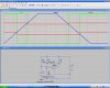
In the attached diagram, the hysterisis is represented by the red trace, which is taken at the comparator's "+" terminal. R2, which is placed the same as R18 in the previous discussion, is allowed to drift between 5k and 20k, as it might if it were a thermistor. At R2=20k, hysterisis is nearly 1V, while at R2=5k it is less than 1/2V. Clearly, allowing this resistor to change in turn changes the hysterisis. You might be able to minimize the effect of drifting hysterisis through the switching band by adjusting the feedback network ( the effect is probably not all that severe in the switching band as it already is ). Personally, I would never do it that way.
I'm sorry but it appears that I've created some confusion. It may have stemmed from when I said I was using an NPN at the comparator output when I really meant PNP. Anyway, the 10Ω 10W resistor shown as R22 in my last drawing is a power resistor, not a relay coil. The power resistor will be used as a heating element and is part of the circuit for testing only.
Upon placing the test circuit in the freezer, the output of the 293 will go low at ~ -5C causing the NPN to conduct. Roughly .5A should then flow through the power resistor causing it to dissipate about 2W of power as heat. That will heat back up the tupperware cotainer that my test circuit is placed in past -1 C and the 293 output will go back high turning off the NPN. Wash, rinse, repeat.
At least that's how I hope an expect it to work. Referrence the explaination of how I plan to do the testing from ye old reply #31 below:
In other news, I think I figured out how I'm going to test the circuit. I breadboarded the comparator circuit and soldered the thermistor to some 2 conductor shielded wire and I grounded the shield. I got a cheap Tupperware container and cut a few holes in it. I mounted the thermistor inside, right next to the temperature probe from my multimeter which is also inside the Tupperware container. Last but not least I placed a 10Ω 10W power resistor inside the container. I also built an output circuit with an NPN and another resistor so when the comparator output is low, the NPN will conduct and the resistor will pump out about 2W.
I hope it should allow me to calibrate the set point and hysteresis band or at least make it equally inaccurate as my multimeter.
Thanks again everyone for the help and explanations. They are really helpful.
Edit: I forgot to mention a somewhat minor but extremly important detail about the testing. I'm going to stick the Tupperware container with everything inside into my freezer.
I'm sorry but it appears that I've created some confusion. It may have stemmed from when I said I was using an NPN at the comparator output when I really meant PNP. Anyway, the 10Ω 10W resistor shown as R22 in my last drawing is a power resistor, not a relay coil. The power resistor will be used as a heating element and is part of the circuit for testing only.
Upon placing the test circuit in the freezer, the output of the 293 will go low at ~ -5C causing the NPN to conduct. Roughly .5A should then flow through the power resistor causing it to dissipate about 2W of power as heat. That will heat back up the tupperware cotainer that my test circuit is placed in past -1 C and the 293 output will go back high turning off the NPN. Wash, rinse, repeat.
At least that's how I hope an expect it to work. Referrence the explaination of how I plan to do the testing from ye old reply #31 below:
Does that clear things up or am I missing something? Thanks again.
The point I was trying to make is what transistor are you going to use to drive the 10R resistor, remember you have only about 4mA base current available for the drive transistor.
Why dont you fit the relay that you are going to use in the final version and use that to switch the 10R heater test resistor.??
At a supply voltage of 5V and a VBE of 1V, the 1KΩ base resistor should allow a base current of 4 mA into the open collector of the 293 comparator. The hFE of the BC369 is 375, so that should allow .5A through the power resistor give or take. The current will be limited by the power resistor not the transistor, I think. Please correct me if I'm wrong about this.
As for the relay, I'm not planning on using a relay in either the test circuit or finished circuit. In the finished circuit, the ouput of the 293 will input into a CMOS NOR gate. The ouput of the NOR gate will drive a opto-coupler and traic arrangemet to turn on AC power to the heater.
I'm confused where the relay is coming from. Should I be using one?
In the attached diagram, the hysterisis is represented by the red trace, which is taken at the comparator's "+" terminal. R2, which is placed the same as R18 in the previous discussion, is allowed to drift between 5k and 20k, as it might if it were a thermistor. At R2=20k, hysterisis is nearly 1V, while at R2=5k it is less than 1/2V. Clearly, allowing this resistor to change in turn changes the hysterisis. You might be able to minimize the effect of drifting hysterisis through the switching band by adjusting the feedback network ( the effect is probably not all that severe in the switching band as it already is ). Personally, I would never do it that way.
First i'd like to say that i respect your opinion and i am happy that you tried to simulate this circuit as that
usually gives us a good idea how it might work out in real life. The conclusion you reached however was
not correct this time because the simulation was not done correctly. As i had said before, if you have 1v
of hysteresis to start with then you have 1v of hysteresis in the end too, as long as all the parts work
monotonically. Let me detail a bit on this...
For the original thermistor we can represent it's resistance change with temperature:
R1=Rx(T)
where
R1 is it's resistance for a given value of temperature T, and Rx is the function that generates this resistance.
For the 'new' added thermistor we can represent it's resistance in a similar manner:
R2=Ry(T)
where
R2 is the resistance of that thermistor for a given value of temperature T, and Ry is the function that
generates it's resistance.
Now what your simulation is suggesting is that we can represent R1 as
R1=Rx(T)
(same as before so that's good) but that we can (or somehow are forced to) represent the second thermistor as:
R2=Ry(S)
where S is some independent step value (and Ry is the generator function).
The difference is that in real life, R1 and R2 are not independent like that but are linked through a common
variable, and that variable is the temperature T. In other words, when R1 changes R2 always follows it
in some predictable manner. To simulate this circuit correctly, we have to change R2 in a way that
corresponds to the value of R1 because they both change in the same way, even though they may have
different resistances and even have different curves (still monotonic of course).
Another way of stating this is for two given temperatures T1 and T2 this means we have:
R1=Rx(T1) and R2=Ry(T1)
****OR*****
we have:
R1=Rx(T2) and R2=Ry(T2)
but we never ever can have:
R1=Rx(T1) and R2=Ry(T2)
because the temperature must be the same for both thermistors.
The only requirements are that the functions be monotonic and they both have roughly the same
thermal time constant, and that the two thermistors be thermally coupled. That's usually easily satisfied by
choosing two thermistors that are of similar composition and using some thermal epoxy and mounting
them inside a case to minimize thermal gradients.
So anyway, to simulate the circuit the way it would really work it would be a good idea to have
R1 change from value1 to value2 and R2 from value3 to value4, but when R1 is at value1
R2 must be at value3, and when R1 is at value2 R2 must be at value4. That's how thermistors
track each other in real life. When one changes the other one does too and in the same direction.
It would be interesting to see a simulation like that if you feel like doing one more, and the hysteresis
will show itself as being only one value.
Perhaps a simpler way to look at this is that if you need the circuit to turn on at say 30 degrees and
off at say 20 degrees and it does in fact do that, then that is 10 degrees of hysteresis.
This site uses cookies to help personalise content, tailor your experience and to keep you logged in if you register.
By continuing to use this site, you are consenting to our use of cookies.

") .
.