mading2018
Member
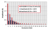
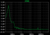
Do anyone know how to check the THD (fft) in a easy way in LTspice?
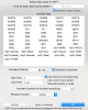
When I press the FFT-button, I got this window popping up. What should I select there?
Maybe an alternative is to do this instead:
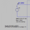
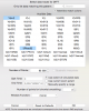
I found somewhere that you need to write a SPICE directive like this:
".fourier {Freq} V(output)"
and then open and check "the spice error log."
according to this source: https://www.diyaudio.com/forums/solid-state/177820-thd-ltspice.html
When I press the FFT-button, I got this window popping up. What should I select there?
Maybe an alternative is to do this instead:
I found somewhere that you need to write a SPICE directive like this:
".fourier {Freq} V(output)"
and then open and check "the spice error log."
according to this source: https://www.diyaudio.com/forums/solid-state/177820-thd-ltspice.html

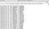
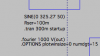


 it is just empty.
")