Continue to Site

Welcome to our site!

Electro Tech is an online community (with over 170,000 members) who enjoy talking about and building electronic circuits, projects and gadgets. To participate you need to register. Registration is free. Click here to register now.

  • Welcome to our site! Electro Tech is an online community (with over 170,000 members) who enjoy talking about and building electronic circuits, projects and gadgets. To participate you need to register. Registration is free. Click here to register now.

Struggling to do my own ELectronic Stuff?

Status
Not open for further replies.
haha, okay will do!

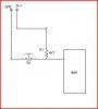
and right, if I think of it as a switch I guess it does make sense. When the LM311 is OFF then the output is floating and we just connect it to the pullup resistor causing it to go to 5v (we now have 5v on the input pin of the PIC).

If the LM311 is ON then the output acts like a ground and will pull the input of the PIC low.

Yes?
 
Here is the changed schematic.
 

Attachments

  • circuit.png
    circuit.png
    33.9 KB · Views: 160
Look at the transistor as the switch in the circuit below.

If the switch is open then there is nothing to pull the input pin high of the picaxe if the resistor is not in the circuit.

Same difference with the transistor in the LM311.

The LM311 acts as the switch.
 

Attachments

  • 08m example.JPG
    08m example.JPG
    16.1 KB · Views: 162
Last edited:
Put some 3mm or 4mm pads for the motor, something chunky you can solder a wire to, you have lots of space there to do so.
 
I see. Then I guess the 'switch' has to be pushed when the inverting input is bigger than the non-inverting input. Because that's when we want our PIC input to go low. When the switch is NOT pushed I guess its floating, and thats when the non-inverting input is bigger than the inverting one?

My confusion comes from not knowing how the output of the op-amp can be floating. From what I know its 0v when inverting input is higher than the non inverting one and 5v when it's the other way around.
 
You are doing well, and have really come to grips with the design software, as you would have found the more you use it the faster you become.

Well done. +++
 
It has nothing to do with the opamp and inverting inputs and non inverting inputs..........it is entirly what the picaxe sees on its input that is the matter here, the picaxe dont give a **** what the opamp do, but only cares about what the input pin of the picaxe receives as a signal on its own input.
 
Do i dare to ask how you intend to take the artwork and put it on to a circuit board??

Photo resist or toner transfer??

Gee............i can see more questions :D
 
ah..right. One step at a time then...

I know that the input on the PIC is high normally unless something pulls it low. (Because of the pullup resistor and the V+). Now the thing that will force it to go low is the switch when it's pressed. So what is the op-amp doing when the switch is pressed?
 
ah ok! THANKS for your help!

(dont get me started on how to ACTUALLY produce the thing lol...nah I will do some more read up and youtube vids first :) )
 
I see no gleeming errors that come to mind so yes have a go at producing a board.

The best thing about making your own boards if you do get something wrong its not hard to change the artwork and make another board.

Good luck.

Pete.
 
Okay, I was thinking of just ordering the PCB from ExpressPCB but it seems like I can only chose to have two boards made instead of just one?

I would like to build it myself, but it does seem to be a lot of hassle. I need to buy a drill and I dont actually have a laser printer either so I guess I need to find one (in a library maybe?)

What do you guys think?
 
I see that Input 3 has no pull-down resistor. That means the input will be floating, with possibly undesirable results, when the push-switch contacts open.

Alec
 
Good point Alec.

Yes input3 on the picaxe should have a pulldown resistor (5 to10K will do)

Pete.
 
Right, all of this should now be done.

The final PCB is attached.

Now 2 questions.

1. How do you know the values of the resistors?
2. I will be ordering the PCB instead of making it (dont have enough money to buy a drill etc) where would be cheapest to make it (I live in the UK).

Thanks!
 

Attachments

  • pcb7.png
    pcb7.png
    25.5 KB · Views: 147
Last edited:
Status
Not open for further replies.

Latest threads

New Articles From Microcontroller Tips

Back
Top