Continue to Site

Welcome to our site!

Electro Tech is an online community (with over 170,000 members) who enjoy talking about and building electronic circuits, projects and gadgets. To participate you need to register. Registration is free. Click here to register now.

  • Welcome to our site! Electro Tech is an online community (with over 170,000 members) who enjoy talking about and building electronic circuits, projects and gadgets. To participate you need to register. Registration is free. Click here to register now.

Struggling to do my own ELectronic Stuff?

Status
Not open for further replies.

fouadalnoor

Member
Hello guys,

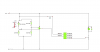
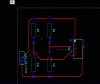
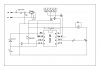
I have my own electronic project that I am trying to build, but I am really struggling with it (its a simple flame detector).

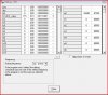
I cant seem to find any straight forward source of information that explains how to use PCB software like ARES (Proteus 7) or Multisim/Ultiboard etc

Anyone can give me some good tips about how to actually attempt to prototype my circuit? I have already physically built it (and it worked to a certain extent), but now that I tried to solder it on to a copper board everything just fell apart...

Before doing this I have actually ruined about 4 chips (PICAXE 08M), many transistors (N-Channel Enhancement ones) and a few other components...

I just feel like I am doing something wrong as I keep making stupid mistakes. Another thing I messed up is the soldering of the components into the copper board...

Can anyone tell me how you guys learned all the practical as well as theoretical stuff? Did you read up a LOT before trying to actually build something or did you just jump in? Where do I find good tutorials on how to create a good PCB (like from initially using simulation software to the PCB software)

I am a little frustrated now so hope you guys can help!

Fouad.
 
but now that I tried to solder it on to a copper board everything just fell apart...

Sounds like your soldering is a problem :confused: as the parts should remain on the board:eek:

It can be a steep learning curve to get the basics in hand when one starts out and only practice makes perfection for some of these skills many of us take for granted now.

The quality of the tools you have make a big difference to the results to, when soldering you need to heat the component leg and the board track evenly till the solder flows smoothly onto both.

There is many "how to solder " tips on the net and several Utube videos, so that should be easy to find.

Can you post a schematic of your circuit so we can help you with the design or the problem areas.
I have done a lot with picaxe so am able to help with coding and problems there too.

Pete.
 
If your circuit "worked to a certain extent" why would you want to solder it up on a PCB? Get a breadboard like this:

https://www.allelectronics.com/make-a-store/item/PB-1680/BREADBOARD-1680-CONTACTS//1.html

Experiment with it until you're happy, then do the board. 90% of what I do never leaves the breadboard

Download LTspiceIV from Linear Technology. It is a fully loaded simulation program that will let you immagineer and not fork over a penny.
 
Sounds like your soldering is a problem :confused: as the parts should remain on the board:eek:

It can be a steep learning curve to get the basics in hand when one starts out and only practice makes perfection for some of these skills many of us take for granted now.

The quality of the tools you have make a big difference to the results to, when soldering you need to heat the component leg and the board track evenly till the solder flows smoothly onto both.

There is many "how to solder " tips on the net and several Utube videos, so that should be easy to find.

Can you post a schematic of your circuit so we can help you with the design or the problem areas.
I have done a lot with picaxe so am able to help with coding and problems there too.

Pete.

Haha, I didnt actually mean the components fell apart, I meant it just didnt work (I am not good at soldering so I probably have to do the whole thing again, much neater...)

I have already prototyped the whole circuit into my Breadboard and it worked more or less as expected (a few issues with noise, but I'm sure when I solder it, it should work)

Hmm... is the easiest way to go from a Breadboard to a more solid board by creating a PCB design (using software such as ARES, or UltiBoard)? or should I just use a copper board (I dont even know its name lol) where you solder the components on a track that already has holes in it...
 
First of all this might go much better if you post a circuit of exactly what you are doing and how it was designed.

This is obviously a continuation of this particular thread which you never posted back in as to the initial PIC problem? You started with motor control with a brief mention of flame detection. Then you left the thread hanging open?

Are the PIC problems resolved?
Can you post the circuit you are using?
Almost works is not a good answer. :)
How exactly did you settle on detecting the flame?

Ron
 
Last edited:
First of all this might go much better if you post a circuit of exactly what you are doing and how it was designed.

This is obviously a continuation of this particular thread which you never posted back in as to the initial PIC problem? You started with motor control with a brief mention of flame detection. Then you left the thread hanging open?

Are the PIC problems resolved?

ah sorry, you are correct.

Can you post the circuit you are using?
Almost works is not a good answer. :)
How exactly did you settle on detecting the flame?

Ron

I have found a work around for the PIC problems (they only occur when I initially turn it on and then it works ok after that)
I will be using a thermistor since it works fine for now (this might change as I improve the circuit down the line.

I will be posting a good schematic of the circuit shortly (I need to change a few things first).
 
I am sure once you get a circuit posted you will get some good help.

Ron
 
Hello Fouad,

You write:

"Anyone can give me some good tips about how to actually attempt to prototype my circuit? I have already physically built it (and it worked to a certain extent), but now that I tried to solder it on to a copper board everything just fell apart... "

- I am sure many people would like to help you, but we probably need a more specific question to be of much use. - If you can identify a particular procedure you are having trouble with, people who understand it can give you a simple step-by-step guide. To ask that more specific question, you may need to troubleshoot your board to identify why it isn't working properly, then someone may be able to suggest a fix.

Anyway, for general recommendations, if you are producing PCBs, I would suggest you stick to photographic methods: transparencies of your track pattern, presensitised copper clad boards, a UV exposure box and developing solution. - I can produce reliable PCBs consistently using this method. And when boards do fail, it is generally because I have done something unwise, like make a track too thin, so it ends up with a hairline crack.

This guy spells it out quite well:

https://www.electricstuff.co.uk/pcbs.html

Other people have reported success with the "toner method". - It has never worked for me, so others who have used it with good results will have to relate their experience.

"Before doing this I have actually ruined about 4 chips (PICAXE 08M), many transistors (N-Channel Enhancement ones) and a few other components..."

- You did not say how you damaged the components you mentioned: Over heating when soldering? - Solder briskly don't leave the iron too long on the joint: in and out rapidly. Heat the joint and apply the solder. Once the solder flows all around, remove it and remove the iron.

Damage done when desoldering? - Use good quality desolder braid, a decent desoldering pump and a sufficiently hot iron. - Don't pull too hard at components when the solder around them hasn't melted fully. - If you do, you could detach a leg, or worse lift a PCB track.

Incorrect polarity? - Insert a polarity protection diode, that way current can't flow the wrong way into your circuit.

If you are working with an unfamiliar component, keep a copy of the datasheet close by: it will show the pinout, so you will know which way round to connect it.

What sort of components are you using? - Surface mount or through hole? - I learned to solder using through hole, and I suspect it's much easier to learn than surface mount.

When using chips, solder an IC socket into your board, then place the chip inside that. - You can't damage the chip by over heating and you can remove it easily should you need to.

Are you using static-electricity sensitive components? - Wear an earthing strap on your wrist when you handle them and discharge yourself by touching an earthed object. - That way they won't be zapped by electrostatic discharge (ESD).

- We don't know what went wrong because you haven't said enough...

"Can anyone tell me how you guys learned all the practical as well as theoretical stuff? Did you read up a LOT before trying to actually build something or did you just jump in?"

I just jumped in, tinkering with everything around me: TVs, radios, tape-recorders, building stuff from magazines and books, etc. Repairing things... the more you do, the more you'll learn.

Actually, it would be a very good idea to do both - get yourself a decent electronics textbook, read through it and do the exercises, then you'll start to learn about the properties of various components. When you're designing, you'll know more or less what to look for.

I found "Electronic Principles" by Albert Malvino, (5th ed) really useful. I'd also recommend "The Art of Electronics" by Paul Horowitz and Winfield Hill.

As SAborn wrote earlier, the only realistic way to get good at soldering is to do it on a regular basis. That way you'll learn to distinguish a good joint from a dry one by sight. A very useful skill.

And, obviously, troubleshoot the boards that don't work as expected - it's tedious and annoying, but just by doing that you might learn what to avoid in the future. For good advice on this area, you may want to read "Troubleshooting Analog Circuits", by the late Bob Pease.

Good luck.

Analogue.
 
Ok, Sorry about all this confusion guys. I was just a little frustrated when I posted this!

Anyway, the circuit diagram is attached to this post now.

I have programmed the chip in the following way:

main:
if input4 = 1 AND input3 = 0 then wait 12 high output0 ;gas and switch ON, wait 12s and Motor ON
endif
if input4 = 0 OR input3 = 1 then low output0 ; gas OR switch OFF, Motor OFF - if the flame is on in the middle
endif
goto main


The whole idea is simply trying to make sure that gas is not leaking from my gas cooker at home. When the thermistor's resistance increases it means the flame is now on and thus the motor turning the nob on the cooker is OFF. When there is no flame (i.e. gas is leaking) the motor is will turn ON, turning the nob which turns OFF the gas.

The switch in the circuit diagram should in reality be replaced by a contact in the nob, so as it turns around it will touch the contact, turning the motor OFF. The reason I chose the 12s wait is because it takes around 10s for the thermistor's resistance to reach about 5k which will turn off the motor. If after that time, the resistance is still 10k then there is definitely no flame and thus the motor should be ON.

Hope this explain more clearly what I am doing.


Now for the problems that I have.

1. My PIC seems to go ON and OFF about 6 times as soon as I turn it on even when I have a 0.1uF decoupling capacitor between the two power pins. This only happens as I supply power to the circuit, but after that it does seem to behave fine. By this I mean I can turn the switch ON and it will react as expected, I turn it OFF and again it reacts as expected. But I always have to initially wait a while before it settles when I power the circuit for the first time. This happens regardless whether I connect the motor to the circuit or not. It will behave like this even when I connect it by itself to my test bed (also attached).

2. I accepted the problem with the PIC and tried to solder the whole circuit from my breadboard into my copper board, using jumper wires. This failed as I tried to make a "bridge" with my connections as I can only connect jumper wire to each pin. While soldering I accidentally connected the wrong pins together (since they are pretty close to each other and I am not good at soldering yet). I then tried to fix this by de-soldering the connections, but I don't have a de-soldering braid and so I messed the connections up pretty badly. After trying to fix it as best as I could I then tested it and of course it didn't work as expected.

3. I am now trying to create a proper PCB by using Multisim/Ultiboard software to simulate the circuit and then produce the PCB. The problem here is that Multisim does not have the PIC that I am using (it only has PIC18F84 and PIC16F84A) but I was able to at least simulate and create half the circuit (attached). I could just add a DIP8 package from Ultiboard which would work. Though I keep getting DRC errors saying "Unused Pin Connected to Copper". I can't find any good tutorials online so I don't quite know how to use Ultiboard yet.


I think the best way to fix the issue's with the PIC and the PCB stuff is to create a PCB design on Ultiboard and then produce the PCB. That way noise might not be a problem as I am not using any long wires then, I am connecting the circuit directly to batteries and by adding a 0.1uF capacitor between the pins of the chip it should work ok. It will also be easier to solder that way and I don't think I will make many mistakes (plus I will get practice making PCB's).

What do you guys think?

Fouad.
 

Attachments

  • GasAlarm.png
    GasAlarm.png
    23.2 KB · Views: 270
  • PCB.jpg
    PCB.jpg
    405.6 KB · Views: 253
  • LD-2 Pencilbox Logic Design A4 Leaflet.pdf
    7.1 MB · Views: 606
First try the following code:

Code:
main:
	If pin4 = 1 And pin3 = 0 Then MotorOn
	If pin4 = 0 Or pin3 = 1 Then MotorOff
	goto main
MotorOn:
	wait 12 'Wait 12 Seconds
	high 2 'Motor On
	pause 500
	DO: LOOP Until pin4 = 0 Or Pin3 = 1 
	goto main
MotorOff:
	wait 1 'Wait 1 second 
	low 2 'Motor Off
	pause 500
	Do: Loop Until pin4 = 1 And pin3 = 0
	goto main
I changed the pinout and pins used from what you had. The code runs fine in simulation and I actually loaded it on a PICAXE 08M to test it. This should give the results you want. Try to keep the code broken down and structured as above.

I did not overly look at your circuit and you did not identify the opamp used?

I have no idea as to the chip cycling at start up? Never had one do that. I use a tiny little board I made up to run and program the little 08M chips that I dug out. Anyway, the above code works so just copy and paste into the PICAXE Programming Editor and play around with it. It should get you started.

Ron
 
Last edited:
First try the following code:

Code:
main:
	If pin4 = 1 And pin3 = 0 Then MotorOn
	If pin4 = 0 Or pin3 = 1 Then MotorOff
	goto main
MotorOn:
	wait 12 'Wait 12 Seconds
	high 2 'Motor On
	pause 500
	DO: LOOP Until pin4 = 0 Or Pin3 = 1 
	goto main
MotorOff:
	wait 1 'Wait 1 second 
	low 2 'Motor Off
	pause 500
	Do: Loop Until pin4 = 1 And pin3 = 0
	goto main
I changed the pinout and pins used from what you had. The code runs fine in simulation and I actually loaded it on a PICAXE 08M to test it. This should give the results you want. Try to keep the code broken down and structured as above.

I did not overly look at your circuit and you did not identify the opamp used?

I have no idea as to the chip cycling at start up? Never had one do that. I use a tiny little board I made up to run and program the little 08M chips that I dug out. Anyway, the above code works so just copy and paste into the PICAXE Programming Editor and play around with it. It should get you started.

Ron


ah thanks! I shall try that now. Also the opamp used is an LM741CN
 
YES!!! It does indeed work! But I dont understand why my code doesnt work. Actually, when I change your code and put the output as output 0 then it does not work and behaves exactly like mine. Now when I used my own code and replaced the output0 with output2 then it works as expected (takes about 30s to start for some reason, but im sure thats due to my code)

The code I used is shown below:

main:
if input4 = 1 AND input3 = 0 then wait 12 high output2 ;gas and switch ON, wait 12s and Motor ON
endif
if input4 = 0 OR input3 = 1 then low output2 ; gas OR switch OFF, Motor OFF - if the flame is on in the middle
endif
goto main


I do wonder why a change of output will change the behaviour so much...
 
As to the code I'll look more at it later. At work now. :)

There are several ways to code things to get what you want.

I would drop the LM741 and use a LM311 as what you really want is a comparator circuit. The LM311 is more suited to what you want, works fine off a single rail and works on 5 volts.

Ron
 
The guy in these forums I know is really good with PICAXE is SABorn, maybe he will be back in this thread. This stuff is far from my forte. :)

Anyway as to Output. I may have this wrong but here is my guess. Output is a syntax:

Syntax:
OUTPUT pin,pin, pin...

- Pin is a variable/constant which specifies the i/o pin to use.

Function:
Make pin an output.

Information:
This command is only required on microcontrollers with programmable input/
output pins (e.g. PICAXE-08M). This command can be used to change a pin that
has been configured as an input to an output.

All pins are configured as inputs on first power-up (unless the pin is a fixed
output). Fixed pins are not affected by this command. These pins are:
08 0 = fixed output 3 = fixed input

So if I do this:
Code:
main:
	If pin4 = 1 And pin3 = 0 Then MotorOn
	If pin4 = 0 And pin3 = 1 Then MotorOff
	goto main
MotorOn:
	wait 12 'Wait 12 Seconds
	high 2 'Motor On
	low 0
	pause 500
	DO: LOOP Until pin4 = 0 And Pin3 = 1 
	goto main
MotorOff:
	wait 1 'Wait 1 second 
	low 2 'Motor Off
	high 0
	Do: Loop Until pin4 = 1 And pin3 = 0
	goto main

I can toggle pin 0 by using low 0 or high 0. Now if we do this:

Code:
main:
if input4 = 1 AND input3 = 0 then wait 12 high output2 ;gas and switch ON, wait 12s and Motor ON
endif
if input4 = 0 OR input3 = 1 then low output2 ; gas OR switch OFF, Motor OFF - if the flame is on in the middle
endif
goto main

We get in trouble because we can't say high or low followed by the syntax output.

Now another quirk I see is that we can code this:

Code:
if b0 > 1 then
goto label
else
goto label2
endif

or we can do this:

Code:
if b0 > 1 then : goto label : else : goto label2 : endif

Both samples will do the exact same thing and run the same. The : character separates the sections into correct syntax for the compiler. I noticed rather than a colon as a separator you have semi-colons ( ; ) used? That won't work.

I generally use the first example if I write code like this stuff. The main reason is it is easier for me to follow and see structure in the code. Not being a code guru or programmer I need to keep things simple.

I also tend to use ' for my remarks which tell me what the hell I am doing. The ' is also very useful if I want to remark out an entire line of code by just placing a ' before the line so when the code runs it ignores the remarked out line.

Hope this helps a little
Ron
 
Last edited:
That does explain it quite well I guess. But the ; are for remarks as well so they don't actually affect the code I don't think. Though using ' would also work (but I cant see the difference between using these two)

Fouad.
 
Hi Ya

If I get time later today at work or at home this evening I'll try a few things and see where it goes. I haven't messed around with a PICAXE in about a year but it was fun to drag the PICAXE stuff out and play around with it a little. Also I am looking at a 3 day weekend so should have time at home to screw around as long as I have the stuff out.

Ron
 
Well Ron i dont know about being an expert in picaxe but your comments were very kind.

For starters with this circuit i would loose the opamp as it is not needed, as the picaxe can do all the work, what we do is read the thermister with an ADC pin...........simple.

For example.

Readadc 1, b1

if b1 > 100 then
gosub motor_on
endif

if b1 < 90 then
gosub motor_off
endif
..........

Try to keep your program broken into lines as Ron has pointed out and as i have done above.

If for no other reason other than i can read it and help you sort the bugs out.
To be honest with you those people who write spagetti code and dont try to keep things neat and in order, i dont even bother to help anymore.

If you dont try to help us being able to understand your code why should we spend the time trying to weed through the mess.
It is like writing a letter and not using full stops or commers and not leaving space between words itbecomesarealmessafterawhile?
Ok enough said on that.

What picaxe are you using, i missed that if you have already said.
What are you using to control the motor power, a mosfet or transistor and what one??

I will draw a quick schematic later of how to do this without the opamp as this is a very simple circuit.

Pete.
.........
 
Nice to see ya back in here Pete. He is using a PICAXE 08M. Makes good sense to drop the op amp. Really no need. I should have seen that as recently I used several 08M chips as flow monitors in a permissive loop.

Ron
 
Here is a basic schematic, i revamped an existing one and left the voltage regulator in the schematic but it is not needed if your battery is under 5 volts.

Try not to use output 0 for your motor as it will do some weird things when you try to download a program to the picaxe.
I think the reason why your chip cycles on power up is you have not got the 22K and 10K resistors in the circuit that are needed in the download circuit, they MUST be in the circuit at all times.
I was not sure what you had connected to input3 in your drawing so added a push switch in there at a guess, also if it was a switch the pulldown resistor was missing (i added a 10K)

What you will need to do is setup this little circuit as i have drawn and run a little test program, so as to show the value of the thermister on screen using "debug" this way you will be able to see the ADC value change as the thermister warms up and to be able to determine what value we need to write into program, as the switch on and off points for the motor.

Here is the test program.
Code:
'#################################

#picaxe 08m

symbol thermister = 4

symbol ADC_value = b1

main:

	readadc thermister, ADC_value  ' (same as .... readadc 4, B1 )
	
	debug
	
	pause 200
	
	goto main

'#############################################


I have added a screen shot of the debug window should you have not seen it before, and as you can see variable B1 is called ADC_value, the number next to it will change as the thermister warms and cools, it is this number we need to know, to when to turn the motor on and off.

The schematic is posted twice, in jpeg for easy viewing and pdf for download.

Pete.
 

Attachments

  • Thermister Schematic.jpg
    Thermister Schematic.jpg
    146.4 KB · Views: 246
  • Thermister Schematic.pdf
    12.1 KB · Views: 194
  • Debug.JPG
    Debug.JPG
    74.1 KB · Views: 242
Last edited:
On further thought of what you are doing or trying to do i am a little confused about the motor operation

The switch in the circuit diagram should in reality be replaced by a contact in the nob, so as it turns around it will touch the contact, turning the motor OFF. The reason I chose the 12s wait is because it takes around 10s for the thermistor's resistance to reach about 5k which will turn off the motor. If after that time, the resistance is still 10k then there is definitely no flame and thus the motor should be ON.

Now what turns the knob on in the first place?

Is the motor turning the knob on and off?
If so, then there is a need to forward and reverse drive the motor, which will need a relay or H bridge of some description to reverse the polarity to the motor.

If all the circuit is to do, is turn the Knob off in the absent of a flame, then the circuit will work as designed, but how do you turn the Knob on with a motor attached to it.

It would be much easier to use a solenoid to switch the gas flow on/off prior to the knob.
Although a solenoid would not be good to run from batteries.

Pete.
 
Status
Not open for further replies.

New Articles From Microcontroller Tips

Back
Top