Continue to Site

Welcome to our site!

Electro Tech is an online community (with over 170,000 members) who enjoy talking about and building electronic circuits, projects and gadgets. To participate you need to register. Registration is free. Click here to register now.

  • Welcome to our site! Electro Tech is an online community (with over 170,000 members) who enjoy talking about and building electronic circuits, projects and gadgets. To participate you need to register. Registration is free. Click here to register now.

Struggling to do my own ELectronic Stuff?

Status
Not open for further replies.
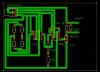
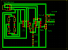
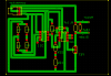
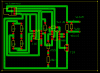
Actually scratch that it works. I have now changed the track size and the copper layer. The only thing left to do is to add the decoupling caps. I dont think I need the download circuit because I only program the chip using the circuit already provided with the chip (look here: **broken link removed**)

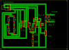
I have the download circuit from that starter pack, and I was thinking of just soldering on the IC Holder to the board so I could just easily take the chip out and re-program it. That way if the chip goes bust then I could also easily replace it. (bad idea?).
 
Last edited:
As i said before the picaxe must have the 22K and 10K resistors of the download circuit in the circuit at all times, weather you use the download circuit or not.

If you choose to not add them you will get erratic behavior from the picaxe, and dont ask later "Why my circuit do strange things"? Because the answer will be you did not add the resistors.
There is many pages on the picaxe forum of people leaving the resistors out and asking why the circuit wont work.

As a rule of thumb for you, dont go smaller than 1mm for your track sizes while you are starting out making boards, as you get more advanced and understand your ability you may be able to go smaller where need be, but keep the bigger tracks where space is not an issue.

Pete.

Ah I guess I can't make any assumptions when I am treating the PIC as a black box. Right I shall add the resistors and the decoupling caps and shall post the circuit on here as well.

Fouad.
 
Okay, I have now added the resistors and the decoupling caps. The thing that I am unsure about is how to connect up the resistors so that the PIC will be in "Out" mode instead of "PROG" mode. I think that when it's in "Out" mode pins 2 and 3 on the header has to be connected together (and this just forming a simple series circuit). Though I am unsure of this (please refer to page 26 of the PICAXE manual).
 

Attachments

  • circuit4.jpg
    circuit4.jpg
    155.5 KB · Views: 154
hi,
Check the LM311 datasheet, pin 7, collector out is o/c, usual to add a pull up resistor to +Vs, a 4k7.
 
hi,
Check the LM311 datasheet, pin 7, collector out is o/c, usual to add a pull up resistor to +Vs, a 4k7.

eh? I don't know what you mean. The output (pin 7) of the LM311 should go to V+ through a 4.7k pull up resistor? I can't find that in the data sheet (why would I need to connect a pull up resistor to the output?)
 
eh? I don't know what you mean. The output (pin 7) of the LM311 should go to V+ through a 4.7k pull up resistor? I can't find that in the data sheet (why would I need to connect a pull up resistor to the output?)

hi,
The output pin #7 on the LM311, is only a transistor collector output.
Without a suitable pull up resistor the output will never go high.
Look at the applications in the datasheet for examples

EDIT:
On some smaller PIC's they have weak internal pull ups, which the program has to enable, a weak pull would mean an external pull up is not required.

I do not use Picaxe, so I am not sure which PIC types they use.?

EDIT2:
12F683 pull ups.
 

Attachments

  • AAesp07.gif
    AAesp07.gif
    28 KB · Views: 159
Last edited:
Very good point Eric.

I have not paid close attention to the circuit design and more to the help with development of the circuit board.

A external pullup as Eric has recommended is a good addition and will not hurt the circuit even if there is internal pullups, which i do not think there is.

Add the 4K7 resistor as a pullup to ensure the issue is covered.

As Eric has said its not the opamp that needs the pullup, its the picaxe that requires it to give a distinct change in output from the LM311.

For referance sake the 08m picaxe is based on the Pic 12F683 chip.

Pete.

Hello,

Yeah I shall add that to the output I guess. I dont quite understand exactly WHY though... is it to do with the PIC having to draw current from the OP-AMP? hmm...
 

Attachments

  • circuit.png
    circuit.png
    41.6 KB · Views: 168
Last edited:
Your circuit board design looks much better with the use of bigger tracks, and the current changes.

One thing i always do is to bring unused pins of components out on a track with a pad at the end, the reason is, often a circuit design evolves, and the need to a extra add on circuit is required so access to spare pins is often very handy.

When you think about it, the cost is no greater to leave the copper behind on the board as it is to remove it.
At the end of the day it all comes down to design techniques that you learn over time or is shared by others more experienced in the process.

Pete.
 
Your circuit change is wrong.

The 4K7 resistor goes from pin7 in your earlier circuit to the 5v+ track.

Hence the ....pullup expression, it pulls the output to 5v+ when the tranistor in the LM311 ts switched off.

The picaxe needs to see a change in voltage on the input pin between 0 volts and 5 volts, when the LM311 is switched on pin 7 it will be 0 volts, but when it is switched off there is nothing to pull the line high so the picaxe will still only see 0 volts on the input pin, hence the pullup resistor, when the LM311 is switched off the pullup takes the input pin of the picaxe high, giving a 0 to 5v change on the input pin of the picaxe.

If you dont understand then email me the express art work and i will change it to be correct for you.

Pete.
 
Your circuit board design looks much better with the use of bigger tracks, and the current changes.

One thing i always do is to bring unused pins of components out on a track with a pad at the end, the reason is, often a circuit design evolves, and the need to a extra add on circuit is required so access to spare pins is often very handy.

When you think about it, the cost is no greater to leave the copper behind on the board as it is to remove it.
At the end of the day it all comes down to design techniques that you learn over time or is shared by others more experienced in the process.

Pete.

Thanks Pete!

I have now added the track pads at the end of the unused pins in case I need them (keep these little tips coming, I can't easily find them anywhere else ;-) )
 

Attachments

  • circuit.png
    circuit.png
    43.1 KB · Views: 148
Your circuit change is wrong.

The 4K7 resistor goes from pin7 in your earlier circuit to the 5v+ track.

Hence the ....pullup expression, it pulls the output to 5v+ when the tranistor in the LM311 ts switched off.

The picaxe needs to see a change in voltage on the input pin between 0 volts and 5 volts, when the LM311 is switched on pin 7 it will be 0 volts, but when it is switched off there is nothing to pull the line high so the picaxe will still only see 0 volts on the input pin, hence the pullup resistor, when the LM311 is switched off the pullup takes the input pin of the picaxe high, giving a 0 to 5v change on the input pin of the picaxe.

If you dont understand then email me the express art work and i will change it to be correct for you.

Pete.

AH, just saw this. Yeah I was thinking it should go up to the V+ buut...donno I guess I find the Circuit Theory part of it a little hard to understand. I WILL get it, though I need to look at the LM311 circuit in more detail...
 

Attachments

  • circuit.png
    circuit.png
    44.5 KB · Views: 145
Last edited:
Its nice to see you listen to advice given, i often feel i am picking at someones good work, but these are the little tips you learn when prototyping a board, as it not always things goes as originally planned, and to give a option of future change is always a good foresight.

There is atleast 1 pin on the opamp you can also do the same with.

Pete.

Woops, didnt see that.

Alrighty, done that now (can't find any space for the last pin on the op-amp though..)
 

Attachments

  • circuit.png
    circuit.png
    33.5 KB · Views: 144
OK, that looks better.

Think of it like a switch, when the switch is off the input pin on the picaxe is connected to nothing or floating as it is called.
So when the LM311 is not on the input to the picaxe is really connected to nothing, so we have a pullup to connect it to 5v+, when the LM311 switches on it sinks the 5v+ from the resistor to ground, pulling the input low.

So the function is the resistor pulls the picaxe input high and the LM311 pulls the picaxe input low, this gives a distinct high low switching of the input pin.

Pete.
 
(can't find any space for the last pin on the op-amp though..)

Not that it is important, but you could move a couple of tracks over and bring to last pin on the opamp out as you have the previous pin.

My whole point was to get you to look at the circuit design, and take a view of ....leave no man behind...meaning the unused pins.

Pete.
 
One more thing that anoys me.............put some bigger pads in for your motor connections. (getting picky now)
 
Also now to try to explain the Pullup resistor...


Looking at this data sheet: **broken link removed**

Q15 will ensure that when its ON the output will go to ground through Q16. This cannot happen if there is no pullup resistor connecting the collector of Q15 to V++.

emm hmm.. still confused a little...too many transistors!
 
Status
Not open for further replies.

Latest threads

Back
Top