Continue to Site

Welcome to our site!

Electro Tech is an online community (with over 170,000 members) who enjoy talking about and building electronic circuits, projects and gadgets. To participate you need to register. Registration is free. Click here to register now.

  • Welcome to our site! Electro Tech is an online community (with over 170,000 members) who enjoy talking about and building electronic circuits, projects and gadgets. To participate you need to register. Registration is free. Click here to register now.

Stacking LEDs

Status
Not open for further replies.
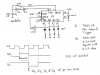
Hi all, I know this might sound beginnerish but I need a 'Non Microcontroller' circuit that will be like an LED chaser; but stacking the LEDs. It would be good if it could do this with about 9 or 10 LEDs per chip, but it doesnt matter, I want to drive 24 LEDs anyway; so the circuit needs to be stackable. So far im thinking shift registers, but i don't know. If anyone has done this before, or has some help for me, please help me out.

Thanks-
Mike
 
Not sure what you mean by stackable, but 555 astable followed by a shift register sounds like the way to go.

You will need a transistor circuit on each channel to convert the logic output from the shift register into current to drive the LEDs.
 
mike11298 said:
If anyone has done this before

I have. That is, if you mean what I think you mean. I have done it several times using something similar to the enclosed diagram. ( note that this is not the actual diagram I used, it's one I've just thrown together to give you the idea )

Have the 555 as a clock pulsing the first 4017, counting from 1 - 6 then moving the second 4017 on 1 then resetting. When the second 4017 counts past 4, it resets. 4 x 6 = 24. :)

Put "555 4017" into google for example circuits of chasers.

Hope this helps.
 

Attachments

  • 24_LED.gif
    24_LED.gif
    19.2 KB · Views: 404
Hi houseofwax,
Yes, a chaser is the basic idea, but i need it to 'stack on' the LEDs instead of one after the other.

eg:

-----
o----
oo---
ooo--
oooo-
ooooo
-----
o----
oo---
ooo--
oooo-
ooooo
etc. etc.

I cant see how the circuit posted does that, but if it does, please tell me how...

-mike
 
Hey dch222,
Thanks for that. im not very good with shift registers, do you know any good sites? Is the 74HC595 what I need? Its the only shift reg. my supplier stocks.

Thanks all
 
Yes, it will do exactly what you want.

Connect:-
the oscillator to SRCLK & to RCLK (pins 11 & 12) via an inverter.

+5 Volt to SER (pin 14).

Gnd to OE (pin 13).

Qh (pin 7) to SRCLR (pin 10) via an inverter.

When the power is first switched on there will be a random pattern in the SR so it will need several clock pulses to shift this out.

If this is undesirable, you will need to install a "power on reset".
 
Last edited:
thats good to hear, i will need power on reset. what is this? and how do i do it? any websites to help me out with shift register stacker? or just the chip itself?
 
mike11298 said:
thats good to hear, i will need power on reset. what is this?
If you don't know what it is, then how do you know you need it?

I explained what it is in my post. It means that the LEDs will start in the all off state rather than a random state.

and how do i do it? any websites to help me out with shift register stacker? or just the chip itself? Just read the data sheet of the 74HC595. It explains how the IC works.
What I described is for 8 LEDs. So if you only need 5 as per your initial post, then take the output from Qe not Qh.

You will need 2 ICs, the 74HC595 and a 74HC14.

The 74HC14 will do the inverting and the oscillator functions. And if you really need "power on reset" then you will need a diode and a resistor wired as an OR gate and a capacitor and resistor for the timing.
 
for the whole thing, or the POR? I think ive got the POR figured out; can you read switcherCAD 3 files? (attached in SwCAD format) Either way, that would be really appriciated.

thanks a lot-
mike
 

Attachments

  • PoR.asc
    581 bytes · Views: 179
yeah, sorry; it was whatever I could throw together at the moment. I would have thought it would be good enough for this kind of application. Thanks anyway for the circuit. It really helps out.
 
mike11298 said:
yeah, sorry; it was whatever I could throw together at the moment. I would have thought it would be good enough for this kind of application. Thanks anyway for the circuit. It really helps out.
You're on the right track with the POR, but you don't need the diode and you do need a Schmitt Trigger as a threshold detector.

What coloured LEDs do you intend to use and how bright do you want them?

The 74Hc series can source/sink up to 25 mA per output, but there is a max package current of 50 mA.

So for 5 LEDs you would be limited to 10 mA max. (unless you include a LED driver)

But I find that about 6 mA is adequate.
 
Well, I need 24 LEDs (3chips) I need them to be the high-intensity blue or green ones, but they will be driven at a very low current (~6mA). I need them about 5mcd.
 
In your post earlier today you wrote this:-

-----
o----
oo---
ooo--
oooo-
ooooo
-----
o----
oo---
ooo--
oooo-
ooooo
So I assumed you only wanted 5 LEDs.

But after reading your post above and your original post you said 24.

So do you want them to be as above but with 24 LEDs? In other words, you want to start at 0 ie. no LEDs lit, then 1, then 2 etc until you have all 24 lit?
 
mike11298 said:
Yes please, I used 5 leds only as an example so I didn't have to write 24 !
That's what I thought.

What voltage is across the LEDs you intend to use assuming a current of ~6mA?

I'll post tomorrow. Good night
 
mike11298 said:
3 volts... I think
To check, I suggest you connect one in series with a 330 Ohm resistor and connect it across 5 Volt and measure the LED voltage. If it is 3 Volt, then 330 Ohm will set the current at about 6 mA. Iled = (5 - Vled)/R

Attached is the basic circuit, configured for 4 LEDs. You may wish to build and test this one before making the full 24 LED version.

I have not included the POR. I have chosen C1 and the 10 M to make the oscillator frequency about 1 Hz. If you want a different frequency, change C1.

I'll draw the full circuit later.
 

Attachments

  • Basic system.png
    Basic system.png
    90.9 KB · Views: 246
Status
Not open for further replies.

New Articles From Microcontroller Tips

Back
Top