Continue to Site

Welcome to our site!

Electro Tech is an online community (with over 170,000 members) who enjoy talking about and building electronic circuits, projects and gadgets. To participate you need to register. Registration is free. Click here to register now.

  • Welcome to our site! Electro Tech is an online community (with over 170,000 members) who enjoy talking about and building electronic circuits, projects and gadgets. To participate you need to register. Registration is free. Click here to register now.

LEDs with negative and positive voltage

Status
Not open for further replies.
Measure from chassis ground to the three points (+) the (-)(+) and (-). Nothing connected. except that (-)(+) connection/
 
Try just a battery, resistor and LEDs to confirm they're working as expected.

Mike.
 
on the lead going to the motor, I put a pair of LEDs wired in opposite polarity (each has a resister wired in).
Are you saying you have them wired like this? :-
Turnouts.png

If so, then IMO that's not the way they should be wired, whatever your reference source says. Depending on the resistances of the motor and R1,R2 you could have more than the rated reverse voltage appearing across each LED. One colour LED may tolerate that, the other colour may not.
 
I have tried using two 9VDC batteries wired positive to negative as common and then having a positive and negative terminal. 9VDC will light the LEDs. no change, blinking on the negative to common connection.
There is no chassis ground. The two power supplies are two prong models plugged into a common 110 VAC power strip.
Again, I am not an electrical guy, but the LEDs are rated at . 015 ma and there are 60 of them. They are in pairs so only half of them will be drawing power at a time, and in the ones that are drawing power some of them will be drawing power from the positive side and some from the negative side of the two power supplies. Right now there are only 7 LEDs hooked up and only 4 turnout motors connected. In my rudimentary calculations I should have enough power once everything is connected.
I have a question, should I have something between the positive wire from power supply 1 and the negative wire from power supply 2 as they are connected to form the common? I am thinking a diode controlling flow from each side to the common terminal?
 
Can you just wire up a single motor, as shown in this diagram, and confirm that it works as expected?

Is it possible that the turnout has a flasher built in, to signal a "divergent path" at the junction? e.g.
jnsig042.gif
 

Attachments

  • single.jpg
    single.jpg
    94.8 KB · Views: 201
I have done all of that. Here is another circuit diagram which is essentially how I wired it:
1599687016824.png

your diagram shows the LEDs out of the power flow to the motor, I do not believe this would make a difference as the LED flashes when connected common to negative.
 
And you did that with the 9V batteries? If there's flashing, then either the LED is a flashing type, or the "tortoise" has some flashing function built into it then.
your diagram shows the LEDs out of the power flow to the motor, I do not believe this would make a difference as the LED flashes when connected common to negative.
I'm trying to remove unknowns from the circuit. The LED will not flash, unless it's a flashing LED when connected across a battery (with series resistor).
 
You say "essentially"; this means there is something different in your actual wiring.
 
Last edited:
The current to drive the motor should not go through the LEDs.

I think this diagram shows what you're after. The two batteries represent your power supplies. The switch controls which way the motor turns.

The LEDs, instead of being in series with the motor are in parallel across it. Depending on the switch position, the top line to the motor is positive and the bottom negative or vice versa. The LEDs should be connected as shown via a single resistor. This clamps the voltage of the reverse-biased LED to forward voltage of the illuminated LED, notably. less than 5 volts most LEDs will tolerate.

One key consideration with this arrangement is that the motor is always energized.


ET-RR.jpg
 
One key consideration with this arrangement is that the motor is always energized.
I'm assuming that the turnabout has limit switches and the LEDs only light when the motor is running and so appear to flash.

Mike.
 
NEWS FLASH . . .I went back through all the comments and decided to retest everything from the beginning. So I hooked two 9 VDC batteries together negative to positive leaving a negative, positive, and common. touched the LED to the terminals and low and behold the LED was steady on both sides when reversed. Just like we have all been saying. I have no clue what I did before. Then I went back to my power supply and it is still flashing negative to common. I connected a volt meter and both sides seemed steady. I went to my treasure chest (all the still functional but discarded stuff) and I found two 9 VDC @ 210 mA power supplies. Hooked them up negative to positive and checked with a LED and both sides were steady on. I wired them into my control panel and WaLa all LEDs are steady when switched.
Now, I bought this pair of power supplies from Amazon, and I will need to replace the two 9 VDC power supplies with two 12 VDC @ 1 A power supplies to supply enough power for all the motors and LEDs. I do not want to repeat the problem, does anyone have a good suggestion on power supplies I can try.
I want to thank all of you very helpful and insightful people and apologize for leading you on a wild goose chase. Prosper from my error and when trouble shooting take your time and do each step correctly and methodically. I would have saved me a lot of time and research.
 
You still have a fundamental problem of powering the motor through the LEDs.

If the power supply is shutting down (as shown by the LED flashing), and it continues to occur if you swap the power supplies (same problem on both power supplies in the "negative" position), it's extremely likely you have an error in wiring or a short somewhere. Switching power supplies have a strong self-preservation instinct. When the current draw is too high, they will shut down and try again in a moment. I believe this was already explained here, but advice is only good when it's what you want to hear.
 
It could be that the negatives of the power supplies are connected to the socket earth pin which will short out the negative side of the supply.

Mke.
 
I'm glad you have found a valid starting point.

pugabral, can you confirm that the turnout motors being used are:

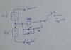
If so, they advise connecting the LEDs in series with the motor, as you originally drew. This gives ~5mA drive current while changing states, and 16mA when at the limits (motor stalled). No series resistors are needed for the LEDs in this configuration. The LEDs will be dimmed during transition.

The 9VDC power supplies being used are two-prong; this means that they are isolated, and have floating outputs. Therefore, any fault condition causing the pulsating output would be due to bad wiring or a defective motor, rather than a power supply being shorted via the other power supply's connection to earth.

Can you test a single motor with LEDs from your power supplies to confirm that they are working? Use the same setup as for the batteries, where you showed it working. At least then you know the power supplies, LEDs and motor are not the issue.

In your full setup, it's quite possible you have some diodes in the wrong position.
 
The switch machine dougy83 linked to in Post 35 has two SPDT switches that show the position of the turnout that it's controlling.
If the purpose of the LED is to show that information, I would suggest using one of those switches to drive your LEDs.

Connect +12 volts to pin 5 of the tortoise.
Connect pin 6 to one of your LED w/resistor to gnd.
Connect pin 7 to the other LED w/resistor to gnd.
This uses only a single polarity of power for the LEDs

This will show the actual position of the turnout that it's connected to, even if there is no power connected to the motor.
This concept is covered in Ap note AN-6000-02 http://www.circuitron.com/index_files/AN/an-6000-02.pdf
 
Status
Not open for further replies.

Latest threads

New Articles From Microcontroller Tips

Back
Top