Continue to Site

Welcome to our site!

Electro Tech is an online community (with over 170,000 members) who enjoy talking about and building electronic circuits, projects and gadgets. To participate you need to register. Registration is free. Click here to register now.

  • Welcome to our site! Electro Tech is an online community (with over 170,000 members) who enjoy talking about and building electronic circuits, projects and gadgets. To participate you need to register. Registration is free. Click here to register now.

SSB Carrier Supression

Status
Not open for further replies.
Don't they produce a lot of distortion?

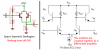
Not if handled properly. They are difficult to bias but the benefit far out weighs the headache of using them. They also provide impedance isolation. Take for instance if you are building a CW transmitter with say 50 watts out. Mismatches between antenna & final or driver stages and final can find its way all the way back to the oscillator especially in class C where you are going for power with minimal stages. The impedance mismatches which could be caused even by rain on the antenna will cause the oscillator to phase shift. A Darlington will virtually eliminate the possibility of this happening.
 
Last edited:
Hi SV! I've collected a lot of parts to build a SSB receiver.
What I don't have is blank pcb, a nibbler or drill to make islands (manhatten), toroids (t37-2 & t50-2 I guess), coil wire (#28 ?), and a good magnifier lamp :)

I also have not decided on band(s) or circuits. I think lower 40 to start. I'd like to use a igmosfet for first mixer and mc1496 for detector. I've built the audio amp (lm380n) already. Have 10 8mhz xtals so will use them for filter and bfo. Should be ok for lower 40 and 80 or 20 in the future, I hope. Even have an 8mhz osc. in a xtal package to play with. It might be the bfo, I'l see.

Whatever you do, don't take any advice or ideas from SV, he doesn't have the slightest clue about any kind of design, and his radio is a complete disaster.

Buy yourself a copy of either the ARRL or RSGB manuals, and build a proper radio.
 
Whatever you do, don't take any advice or ideas from SV, he doesn't have the slightest clue about any kind of design, and his radio is a complete disaster.

Buy yourself a copy of either the ARRL or RSGB manuals, and build a proper radio.

Well spoken from the guy who don't build anything.

Mike, how do you conclude that a Darlington is no good at rf when they switch several times faster than CE amps? Amazing. That points right to a Darlington being an optimal choice. Sure you can use an emitter follower but they come in so handy for that beta X beta current gain. The next CE will need much less work. Plus they have a very stiff current source almost locking the impedance down at that point.

I guess my receiver really sucks when I'm sitting here listening to 2 watt portable stations in Australia from here in Atlanta GA USA. I'm laughing all the way to the grave.

Ham...36 years...me<----WA4BJO

Don't listen to Nigel, he's just a boob.

Oh, by the way. I'm using nothing but a two wire dipole (inverted V). No beam action here.
 
Last edited:
Here's the portable station I was listening to tonight: QRZ.COM Callsign VK1GG

I see he has some stuff listed about his antennas, but I heard him say he was in the bush and had two wires strung between trees.

I'm listening to a guy in Puerto Rico right now....what a crappy receiver.
 
Last edited:
In my apartment I'm afraid I won't hear much. I'll have to go to a park or waterfront to try to get away from all the !@#$%^& RF interference. Everybody has multiple RF noise generators around here. I suspect the ADSL in the phone lines also contributes. It's very depressing trying to listen to the ham bands on a Sony ICF-7600DS. 25 years ago it was more effective.

I know most of the general concepts of receiver design but don't have experience with toroids. 30 years ago when I made a SSB receiver I used Miller coil forms. So, SV, you suggest #36 wire. Should I get other sizes too for receiver work?
I think I'll avoid broadband to use a variable tuning preselector. I'll also try a variable front attenuator instead of a switch. Not really sure. A minor point.
The first mixer is the pivotal part of the design as I see it. If I use an active mixer I probably don't need an RF amp in front. Just a very good filter. If I use a Mini-Circuits diode ring I'll want an RF stage ahead of it. The antenna will most likely be a few feet of wire.
After that, the VFO will be the real challange.
 
Darlingtons work very well in rf. A Darlington is actually an ECL device and they switch faster than CE amps. Thats why cray computers use ECL in the data & address busses.
No.
A darlington transistor is very slow and is hopeless at radio frequencies. I won't use them for high quality audio. The problem is that the second transistor "floats" off slowly.

An ECL logic circuit is very fast because it uses an emitter-coupled differential amplifier that is not allowed to saturate. It is completely different to a darlington, but The Space Varmint draws his darlingtons with one transistor backwards so it resembles the look of an ECL differential amplifier.
 

Attachments

  • darlington vs ECL.PNG
    darlington vs ECL.PNG
    24.3 KB · Views: 198
I've had really poor results using darlingtons for RF, too. You can get some improvement adding a pull-down resistor to the base of Q41 there, but they still aren't super-fast.
 
In my apartment I'm afraid I won't hear much. I'll have to go to a park or waterfront to try to get away from all the !@#$%^& RF interference. Everybody has multiple RF noise generators around here. I suspect the ADSL in the phone lines also contributes. It's very depressing trying to listen to the ham bands on a Sony ICF-7600DS. 25 years ago it was more effective.

I know most of the general concepts of receiver design but don't have experience with toroids. 30 years ago when I made a SSB receiver I used Miller coil forms. So, SV, you suggest #36 wire. Should I get other sizes too for receiver work?
I think I'll avoid broadband to use a variable tuning preselector. I'll also try a variable front attenuator instead of a switch. Not really sure. A minor point.
The first mixer is the pivotal part of the design as I see it. If I use an active mixer I probably don't need an RF amp in front. Just a very good filter. If I use a Mini-Circuits diode ring I'll want an RF stage ahead of it. The antenna will most likely be a few feet of wire.
After that, the VFO will be the real challange.

First of all I would build something resonant at 50 ohms for your favorite band and feed it through a piece of coax. That way you can work out a good preselector which will help reduce the noise a great deal.

Those ideas you have for the front end and mixer sound great. Whatever you are comfortable with. I think I would leave in a single stage rf front end amp. You can always attenuate it. A good CE amp will help keep the impedance low.

The only reason I recommend 36 gauge is because of the size. Anything from 30 to 36 because the number 26 would be a bit thick and you may not get enough turns.

Toroids are a blessing, believe me. I have built without them and too hard to prevent splatter and feedback etc. They really do have self shielding properties but don't get too confident. Like I was saying. About no more than four stages then shield it and run the output into another shielded section through some small coax like RG-174-U. Even 50 ohm audio cable is OK as long as it has outside braid which can be obtained from Radio Shack.
 
I've had really poor results using darlingtons for RF, too. You can get some improvement adding a pull-down resistor to the base of Q41 there, but they still aren't super-fast.

You can either take my advice or leave it. At this point I really don't care. I'll shoot you straight and after that it's up to you but Audioguru is dead wrong on this one. ECL is emitter follower.....period and it switches much faster than CE amps and all the reasons I told you they are highly desirable are true. So don't believed me. I've only been building a good 15 plus years.

Darlingtons are great rf circuits.
 
Last edited:
So, as usual, the rest of the electronics world is wrong, - and SV is the only correct person in the entire world - makes you wonder why he's got a 36 page thread about problems trying to get his wonderful radio working decently? :p
 
No.
A darlington transistor is very slow and is hopeless at radio frequencies. I won't use them for high quality audio. The problem is that the second transistor "floats" off slowly.

An ECL logic circuit is very fast because it uses an emitter-coupled differential amplifier that is not allowed to saturate. It is completely different to a darlington, but The Space Varmint draws his darlingtons with one transistor backwards so it resembles the look of an ECL differential amplifier.[/QUOTE

Nothing turns off Q41...oh brother, where do you the signal output comes from on Q41 idget?

Also even in audio it has become common practice to use Darlingtons for speaker drivers instead of using audio transformers. Integrated packages like the TIP120 are good for this.

The whole trick to using them in rf is to match the impedance. It's very simple. The input Z is R1 / R2 and the output impedance is RE. They perform a whole host of very useful and desirable functions in rf as I mentioned above.

Oh but I can't make a receiver. My crappy receiver only pulled out a 5 watt station form Australia one night and a 2 watt station from Australia the next. Now nit pick away. Jealousy only makes you look stupid.
 
Space Varmint,
I showed your slow darlington emitter-followers and I showed an extremely fast ECL gate with its emitters coupled together. They are completely different.

Darlington emitter-followers are not the same as an ECL differential amplifier.

Guess What ECL means? Emitter Coupled Logic. The emitters are coupled together.
Your darlington emitter-followers have the base of the second transistor connected to the emitter of the first transistor and their emitters are not connected together.

A TIP120 darlington has built-in resistors to turn off the transistors as fast as possible. Your darlingtons have nothing to turn off the second transistor. It slowly floats off.

The datasheet for the TIP120 darlington transistor shows that its current gain is half at only 50kHz and is 1/10th at only 200kHz. It is 1/100th at 800kHz.
It was used in very poor quality cheap stereos about 30 years ago.

Oh, so all configurations are the same? My my how you knit pick to try to prove yourself right since you can't make a radio. All you got to do is read and learn. What do you think emitter follower is? It is the basic building blocks of ECL. ECl is based on emitter follower. Let's go back to electronics 101. You just got to prove me wrong about something...don't you?

Hey guru. If you study real hard, you might be able to make a crystal set. Let's see, I made my first 3 transistor radio when I was about 11 years old. At least get your ham ticket. Stop bashing me....buzz off!

Basic Electronics.....transistors switch faster in emitter follower configuration.....HELLO?
 
Last edited:
Here's the problem.....

You can study all the theory you want but sit down and actually build something. Trust me, it's a whole different ball game. Oh, the theory will apply but you will find yourself flying through material when you start building. It's the real thing.

So I got a couple of people who ask a few questions which I love. I will share all that I have with you. Flat5 has done building before so I dare say he has one upped all you guys by a goodly amount. And another guy asks about some books. We are here to share information, not argue like little jealous children. If I'm wrong or I don't know, I will tell you so. Sometimes I love to be wrong and wear egg on my face so I remember it. But I will be polite to others. I like people and I am all to willing to help if I can. And yes, it is right flattering for someone to ask you a question, but I don't believe in ego. It is a snare! I just like to share common interest with people I think of as friends. Screw all the arguing.
 
Here is a quote from an article.
Darlington pair transistor circuits are not normally used for high frequency applications. The Darlington pair is inherently relatively slow because the base current for the output transistor cannot shut off instantly. As a result Darlington pairs are generally used in low frequency applications including in power supplies or areas where a very high input impedance is needed.

Here is link to article.
Transistor Darlington Pair :: Electronics and Radio Today
 
"...I would build something resonant at 50 ohms for your favorite band and feed it through a piece of coax. That way you can work out a good preselector which will help reduce the noise a great eal."

I think you are saying make an RF signal generator for test urposes.

"...I would leave in a single stage rf front end amp. You can always attenuate it. A good CE amp will help keep the impedance low."

It would only be a few more parts between filter sections and might make matching easier on the output going to the mixer.
I could maybe use resistive networks and not worry about gain so much at that point in the circuit. Lots to think about.

I thought #36 wire would be hard to work with so #30 would be best. I really don't know. For VFO the biggest wire usable is best, right? I'm thinking about frequency drift.

I also have some ceramic resonators for 8mhz.
That might make a tunable BFO quite easy.
I don't like fixed BFOs :) I like to play with them.
People and their transmitters sound different.
I like variable BFOs.

BTW, no Radio Shack in Holland. Not since about 1985.

Also, I'm not ahead of these engineers :)
I used to build stuff and worked in electronics in the 1970s and 1980s. Now I have real trouble seeing detail and don't have the tools and equipment I used to have. I do hope to build this receiver though. It's important to me. Don't really know why :)
 
Last edited:
Flat5, I am passing on a message from "Space Vomit" who says that he is locked out of this/these forum(s). Could you please let him back in.

His message to me can be found here.
Aaron's Homepage Forum - Radio Newbie

He does not seem to be locked out from what I can see. I like some of his post on that forum though. The laser beams from space causing global warming was a pretty good one, lol.
 
I heard that his 5 watt SSB signal was picked up by aliens and they came and abducted him to find out all about our radio technology. They then plan on using it against us, should we be worried?

Lefty
WA6TKD
 
Status
Not open for further replies.

Latest threads

New Articles From Microcontroller Tips

Back
Top