Electro Tech is an online community (with over 170,000 members) who enjoy talking about and building electronic circuits, projects and gadgets. To participate you need to register. Registration is free. Click here to register now.
Welcome to our site! Electro Tech is an online community (with over 170,000 members) who enjoy talking about and building electronic circuits, projects and gadgets. To participate you need to register. Registration is free. Click here to register now.
I am working on generating SSB modulation through phasing method.
Please Can An expert in the field direct me how to generate 90 degrees phase shift for the carrier? If needed The source voltage is 15V.
Thanks
Thanks sir, Actually I already have seen that link and want to implement it. I just have a trouble on its carrier phase shifter circuit. I Think it could be simpler than what it is now!
Did you ever tried to make the SSB circuit in your link?
There is a CMOS astable chip which is able to generate two identical 50% duty cycle square waves just having 180 degrees out of phase. Can I use it and add a FF or a circuit to it so that generate a 90 & 270 degrees out of phase for the said SSB generator too?
two identical 50% duty cycle square waves just having 180 degrees out of phase. Can I use it and add a FF or a circuit to it so that generate a 90 & 270 degrees out of phase...
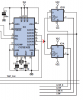
quadrature carrier supplies are derived using 74HC(AC)74 . It is true that the input would be at 4X
a diagram is attached courtesy Elektor magazine, thanks to the author Burkhard Kainka. Published in https://www.elektor.com/magazines/2007/may/software-defined-radio.91527.lynkx May 2007 issue (elektor software defined radio), the entire article is free for download for the members who register .
@dr.power,
at what frequency you need to use this phase shift generator?
if the frequency is Higher than 8 or 10MHz, i fear 40xx series wont be suitable and you have to resort to 74HC or 74AC versions,
Phil Ric's SDR TX appears interesting and you can clearly see that he used 74AC 74.
in the front end also, i suggest to use 74HC instead of 74LSxx
@Nigel Goodwin,
perhaps after all the modulation \ quadrature mixing is over , one can have a filter to remove harmonics, and the SDR designs of Transmitters are not uncommon now a days. However, I am not a HAM licensee , though I worked in RF field in Indian telecom scenario.
The Purpose of this thread is to see if it is possible to create a such phase shifter using 4047 and a FF or so?
Actually I prefer it because it has a "built-in" oscillator and is able to create a nice 180 degrees out of phase output...
Additionally please somebody enlighten me about a accurate oscillator for the above circuit.
I my self wanted to use 4047 But I am not sure if it is an accurate oscillator or there is a better option?
Please help
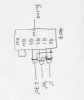
i suppose that it is AGC pre amplifier for the MIC input and even includes necessary pre empasis.The output of second op amp section is detected and the resultant DC varies the impedance of the FET. The FET in parallel to 270K, moderates its value and in turn the gain is automated.
Regarding oscillator element for your design, perhaps you are likely to get 1.820MHz crystal or resonator that provides a 4X signal to get 455KHZ quadrature signal. we may use any schemit inverter gate with the crystal in the path as oscillator. you might use 4093chip and with one gate you can achieve the osc, though buffering suing another gate would free the output from load
The best way is to use a divide by 4 arrangement. It doesn't care about input duty cycle. This gives 90 degree LO shift over wide frequency range. If you have an assured 50% input duty cycle you can create 90 degree shift with divide by 2 (one /2 is on pos edge, other /2 on neg edge). Any duty cycle variation will result in shift in 90 degree phasing.
Are you meaning it is an audio gain controller having pre emphasis? But as I now new electret mikes do not need pre emphasis, Right? Maybe Audioguru knows more about that? The main question is why they needed to use pre emphasis on that circuit? Due to mike or something else?
The output of second op amp section is detected and the resultant DC varies the impedance of the FET. The FET in parallel to 270K, moderates its value and in turn the gain is automated.
Regarding oscillator element for your design, perhaps you are likely to get 1.820MHz crystal or resonator that provides a 4X signal to get 455KHZ quadrature signal. we may use any schemit inverter gate with the crystal in the path as oscillator. you might use 4093chip and with one gate you can achieve the osc, though buffering suing another gate would free the output from load
Then Is it possible to change the frequency of such an oscillator by say a factor of 10%?
I myself think of using a 4047 Astable chip. It gives a very accurate 50% duty cycle on its 10 & 11 pins which are 180 degrees out of phase, I just wondering if I can produce the 90 and 270 degree signals some how too?
This site uses cookies to help personalise content, tailor your experience and to keep you logged in if you register.
By continuing to use this site, you are consenting to our use of cookies.