Gregory
Member
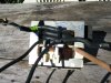
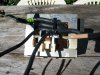
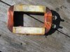
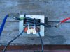
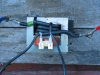
I have made a spot welder from a microwave transformer .
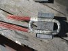
I removed the primary windings and rewound the winding with 10mm wirer there is 3 raps of wirer on the iron cor.
The volts in the primary is 240 V and the secondary is 3.4 volts.
I do not know what current it will produce .
But I am not happy wit the results.
How can I improve the welding current.
Do I increase the voltage.
Or increase the the windings This is can not be done unless I change the wire size on the secondary.
I would I be better to implement a cap.?

") What winding have you removed?
What winding have you removed?