Tallon Karde
New Member
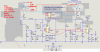
I am working on a project to build a motorized actuator for a pop-up target system similar to what the military uses, accept this would be for 3D archery. It has been a long time since I worked with electronics on the component level. I designed a control circuit for basic automated operation of of the motor but I don't know if it will work or what value my components should be. can anyone give me some assistance on this? see the attachment for details.
")