Continue to Site

Welcome to our site!

Electro Tech is an online community (with over 170,000 members) who enjoy talking about and building electronic circuits, projects and gadgets. To participate you need to register. Registration is free. Click here to register now.

  • Welcome to our site! Electro Tech is an online community (with over 170,000 members) who enjoy talking about and building electronic circuits, projects and gadgets. To participate you need to register. Registration is free. Click here to register now.

Solenoid switch circuit verification

Status
Not open for further replies.

richacm

New Member
Hi can someone verify my little circuit please.

When I switch on I need 0.1A to go one way through a solenoid and when I switch off I need the 0.1A to go the other way.

Much appreciated.

Craig
 

Attachments

  • SolenoidSwitch.gif
    SolenoidSwitch.gif
    7.1 KB · Views: 439
Can you use a center off double pole switch? Really easy to reverse current with one.
**broken link removed**
Your circuit has floating bases, you may want to add a couple more resistors to keep the tied to power & gnd.
 
Last edited:
Yeah I can use what ever I like....I just thought transistors would work ok.

Instead of having a manual switch I am going to send 5V directly to the Base of the transistors from a PIC chip. I.e. to turn ON I send 5V to the Base of the ON transistors and OFF sends 5V to the Base of the OFF transistors.

Thanks.

Craig
 
Last edited:
You need two PNP and two NPN transistors.

Thanks for that...missed the PNP, NPN relations.

Attached is new circuit. I still have floating bases though as pointed out by blueroom....how do I stop that?

Cheers,

Craig
 

Attachments

  • SolenoidSwitch.gif
    SolenoidSwitch.gif
    7.1 KB · Views: 371
Sorry I didn't notice before... you also need to swap the PNP emitters with one another.

Your bases won't be floating when you hook them to the PIC.
 
Sorry I didn't notice before... you also need to swap the PNP emitters with one another.

Sorry I don't follow that one. The PNP Emitters go to either solenoid terminal to make the current go from 0.1A one way or 0.1A the other way....that's correct isn't it? Oh that little symbol in front of the 0.1A is a ~ for approximate. It looks like a "-" negative when its small.

Your bases won't be floating when you hook them to the PIC.

Ah ok.
 
Last edited:
I think I know what you mean....I needed NPN transistors didn't I?

As in the diagram.
 

Attachments

  • SolenoidSwitch.gif
    SolenoidSwitch.gif
    7.2 KB · Views: 176
Transistors 2 and 4 should be PNP. Emitters 1 and 2 should be connected together. Emitters 3 and 4 together too.

Sorry I took so long to reply, my internet at home is down.
 
Last edited:
But if 1 and 2 emitters were connected together then the current would go straight to ground wouldn't it? I wouldn't get any current going through the solenoid.

Sorry I am not following what you mean.
 
Last edited:
Here's what I mean: The two inputs are MCU ports. Won't work with a switch without additional resistors. Probably should replace the 1Ks with 220 or 270 ohms.
 

Attachments

  • hdrive.JPG
    hdrive.JPG
    14.5 KB · Views: 206
Last edited:
Here's what I mean: The two inputs are MCU ports. Won't work with a switch without additional resistors. Probably should replace the 1Ks with 220 or 270 ohms.

Thanks, but when the Off/On switch is on wouldn't there be a straight path down to ground missing the solenoid?

EDIT: I think I am not clear on what a PNP transistor does. Is it the opposite of an NPN? In that it is on when the Base is Low and Off when the base is High?
 
Last edited:
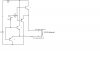
When the top input is high, T1 acts as an emitter follower and its emitter is at approximately 5V-Vbe. T2 is not conducting. When it is low, T2 acts as an emitter follower and its emitter is at approximately GND+Vbe, and T1 is not conducting.

Similarly for the other input, with T3 and T4 respectively.

Note that as emitter followers T2 and T4 don't turn on unless their bases are actively pulled towards GND.

Consider the following 4 cases:
A) HIGH/LOW - T1 emitter pulls to 5-Vbe. T4 emitter pulls to GND+Vbe. Coil receives +5V-(2*Vbe).
B) LOW/HIGH - T2 emitter pulls to GND+Vbe. T3 emitter pulls to 5V-Vbe. Coil receives -(+5V-(2*Vbe)).
C) LOW/LOW - T2 emitter pulls to GND+Vbe, T4 pulls to GND+Vbe. Both ends of coil at the same potential.
D) HIGH/HIGH - T1 emitter pulls to 5V-Vbe, T3 emitter pulls to 5V-Vbe. Both ends of coil at the same potential.
 
Hi,

thanks for the explanation...it made sense.

I tried it out on my solenoid and it worked fine when I changed the bases from 5V to 0V on either transistor. I then connected it up to my PIC chip and drove the base via that. However this didn't work.

I am setting PORTE.0 and PORTE.1 as the two outputs. I set PORTE.0 to $FF and then PORTE.1 to $0 and I would expect the bases to be 5V on RE0 and 0V on RE1 however RE1 carries a voltage of 1.4V and instead of the negative terminal being 0V it is 2.2V and the positive is 4.9V going in to the solenoid. Is there any reason why this would be?

Thanks,

Craig
 
My actual voltage differential across the solenoid is only 2.5V either way....I'm a bit confused as to why? Any ideas how to correct this?

Thanks
 
My actual voltage differential across the solenoid is only 2.5V either way....I'm a bit confused as to why? Any ideas how to correct this?

Thanks

G'day Rich,
Which circuit version are you using, any chance of a posting, of the latest.?:)
 
Status
Not open for further replies.

Latest threads

New Articles From Microcontroller Tips

Back
Top