Continue to Site

Welcome to our site!

Electro Tech is an online community (with over 170,000 members) who enjoy talking about and building electronic circuits, projects and gadgets. To participate you need to register. Registration is free. Click here to register now.

  • Welcome to our site! Electro Tech is an online community (with over 170,000 members) who enjoy talking about and building electronic circuits, projects and gadgets. To participate you need to register. Registration is free. Click here to register now.

Help activating a solenoid via a capacitor when power is cut

clinot

New Member
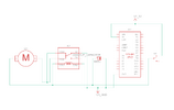
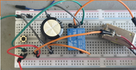
The goal is to create a circuit that activates a solenoid when the supply power is cut, using power stored in a capacitor. So far the issue I have been running into is that the relay is energized by the capacitor when power is cut, and the solenoid on NC remains stationary. If the ground for the relay coil is removed at the same time that supply power is cut, then the circuit functions as intended, but so far I have only been able to do that with a manual button/unplugging a wire. Ideally it would all function on a single power input, rather than needing a control input as well.

Thank you for the help!
 

Attachments

  • FailsafeDiagram.PNG
    FailsafeDiagram.PNG
    28.7 KB · Views: 82
  • OneButtonCircuit.png
    OneButtonCircuit.png
    4 MB · Views: 79
The problem is, the capacitor voltage is keeping the relay closed until the capacitor is nearly discharged.

To prevent that, connect the capacitor only to the solenoid but not the relay.
Isolate that capacitor-solenoid connection with a Schottky diode to the power switch (anode to switch).
The relay coil stays connected to the switch.

That way, the capacitor will charge through the diode to the supply voltage, but the relay will turn off immediately when the power is removed since the capacitor voltage is blocked from the relay coil.

To minimize the surge current through the diode when the switch is turned on, add a 10 ohm resistor in series with the diode.
 
Thank you for the help! The discharge through the relay makes sense, though I'm not quite getting how the diode will solve the problem. Could you help elaborate a bit, or share a simple diagram?
 
Last edited:
The above circuit will momentarily apply voltage to the solenoid as the capacitor charges, during the few tens of milliseconds it takes for the relay contacts to open when power is applied.
It that's a problem, increasing the value of R1 will reduce the applied voltage during that time.
 
Last edited:

Latest threads

New Articles From Microcontroller Tips

Back
Top