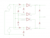
OK, finally got caught up. Here's a circuit that I've been thinking about. I've been trying to simplify it, but this is the best I could do. Note I change dot LM339 comparators, and since they are open collector outputs I had to add pull up resistors (R11 and R12).
The two outputs, LEFT and RIGHT go to the MOSFET gates Q3 and Q4 depending on which direction they actually move the motor.
How it works:
R9 and R10 form a voltage reference of about 400mV. I chose this as my arbitrary darkness criteria. Reduce this by decreasing R10.
R11 and R12 provide the gate voltage to the MOSFETs. This is not fast enough for high speed circuits but is perfect here.
R5 and R7 (and similarly R6 and R8) prevent their respective comparators from triggering on tiny changes of light. The values shown of 10K/100K make that criteria about 9%. If B and A are within 9% of one another the motor rests. You can reduce this band by decreasing R5 and R6.
Logically:
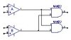
U1B is LOW if B isn't substantially brighter than A.
U1D is LOW if B < 400mV, that is, if B is too dark.
If neither U1B nor U1D are LOW (That is, B is bright enough AND B > A) then RIGHT is pulled up via R12 turning on the MOSFET.
U1A is LOW if A isn't substantially brighter than B.
U1C is LOW if A < 400mV, that is, if A is too dark.
If neither U1A nor U1C are LOW (That is, A is bright enough AND A > B) then LEFT is pulled up via R11 turning on the MOSFET.
")