Continue to Site

Welcome to our site!

Electro Tech is an online community (with over 170,000 members) who enjoy talking about and building electronic circuits, projects and gadgets. To participate you need to register. Registration is free. Click here to register now.

  • Welcome to our site! Electro Tech is an online community (with over 170,000 members) who enjoy talking about and building electronic circuits, projects and gadgets. To participate you need to register. Registration is free. Click here to register now.

Solar Tracker Circuit Is Giving Me Issues - Appreciate Anyone's Help

Status
Not open for further replies.
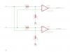
Okay so I placed the diode back in the circuit, but running into the issue I had earlier when I stuck it in the circuit as you'll see in the attached schematic:

screenshot.1..jpg space space space space screenshot.2..jpg


When I hooked up a multimeter to it, the volts (ex. 2.30pV) were so low that I doubt the motor would even move at all, but I believe with Multisim, the LEDs will turn on no matter how low or high the voltage is....my theory..

Here is the circuit with two multimeters hooked up, and as you can see, one side of the motor will continue to run while the other is not running, and both switches are down, so that's not right at all :) Hmmm what could be wrong...
screenshot.3..jpg
 
Last edited:
well, that's right... one side will be 12V and one side will be near ground... it won't be at ground because of the R ds on of the FET.
what the meters are telling you is that Q2 and Q3 are on... Q2 is sourcing current to the motor and Q3 in sinking the motor current to ground.

the problem is, when both opamp outputs are sourcing current and both sides try to come on, the clamp prevents one side from coming on and one side will be left on. This will send it off alignment, where it will then drive itself back on. This may cause hunting.

but judging from the circuit, when both inputs are equal, there should be NO current flow from the opamp, but FETs don't work on current, they work on voltage. However, we can't gaurantee the voltage level... there are no pulldowns on the FET gates. They would be left 'floating'... once they are turned on the gate charge might hold them on for how long? This is why leaving unused CMOS gates is a problem...
 
Last edited:
Well when both switches are enabled, that indicates that the sun is directly in the middle of both Phototransistors, so, if one side of the motor is getting 11v, it's going to turn the motor left/right which will then activate one of the gates, and repeat itself, which seems like i'll be wasting power that way...and drain the battery much quicker?

I'm wondering if there is a way to make it so that when both switches are enabled (sun in the middle of both Phototransistors) the FETs act the same way as to if both switches were disabled...hmmm

As of right now in the current circuit we have, the tracker only turns 1 way, which can't be right. Refer to the short clip below for a demo:

**broken link removed**

As you notice, the Orange LED never goes off no matter what state the phototransistors are in.
 
Last edited:
rs14smith - have a look at the following. It has a pretty good explanation of H-Bridges.
H-bridge - Wikipedia, the free encyclopedia
There are a few links towards the bottom with further examples too.

Good luck!

Well I have the basic logic down, I just need help confirming what I have currently in the schematic will work or not with what I'm trying to use it for.

I'm thinking of just going ahead and ordering the pieces currently in the schematic and see how it does in the meantime.
 
At some point you'll have to make the op amp input real. The LM324 is not well behaved with unconnected inputs.
 
At some point you'll have to make the op amp input real. The LM324 is not well behaved with unconnected inputs.

What do you mean by make the op amp input real? You mean like a real live test, known to me as "hardware test" ? If so, yeah I've already done that, I already own the current op amp in the schematic and used it on my breadboard many times. But mneary, based off my last schematic I drew up, in theory, should that rotate left and right, as for some reason as I was explaining to someone, when I have that diode in there, it seems to only want to turn in 1 direction, and I made a short little clip on it as well. So based off that simulation, I do not see how it would work on a hardware test as well...
 
Last edited:
I mean that when the op amp is shown with unconnected inputs you leave the simulator to guess. You should really simulate with reasonable values and without the switches. Select new values for V1 and V2. Try 0.95V and 1.05V. Swap them to test both situations. Your motor should go one way if V1>V2 (U1b, Q3, Q2) and the other way if V1<V2 (U1a, Q4, Q1).

In the diagrams of post #41 you only have the situations where both inputs are equal: either both 1V or both open. The op amp output should be unknown but your simulator has both op amp outputs high. And with the LEDs in place without limiting resistors your simulator should be showing Both Q1 and Q2 on regardless of the other inputs.

When you're happy with this we'll work on generating a dead zone so that when V1 and V2 are equal, the motor rests.

Al-righty. The main reason I did the switches is so I would not have to manually enter values in like you suggested I do, but considering you know way more about this than I do I did what you recommended lol below:

One Side With More Sunlight:
screenshot.1..jpg

Other Side With More Sunlight:
screenshot.2..jpg

No Sunlight (Night Time):
screenshot.3..jpg

Equal Sun Light (Dead Zone):
screenshot.4..jpg

As you can see, when it's Night Time, my motor will continue to rotate in one direction which will drain the battery over night. Of course the DeadZone we'll fix next, so really the Night Time state needs work as well :)
 
I think this creates your dead zone.

When 0.91*A > 1.00*B then U1A (+) > U1A (-) and LEFT is activated.
When 0.91*B > 1.00*A then U1B (+) > U1B (-) and RIGHT is activated.

If I did this correctly, then when A and B are close, then neither LEFT nor RIGHT is active and the motor rests. This will happen at night, as well as when the panel is aimed properly.

[edit] oops it won't work at night when both inputs are zero. Corrected diagram follows when I think of something. This isn't easy![/edit]
 

Attachments

  • Solar-h..png
    Solar-h..png
    5.9 KB · Views: 455
Last edited:
Okay, so I tried the schematic you drew up, but it's producing the same results, and I noticed you changed the OP-Amp in your schematic, so I even tried changing mine to match, and it again produced the same results as before.

I was forced to remove the 100K Resistors you have in the schematic as my phototransistors will only produce up to 1v, so a 100K Resistor was preventing the OP-Amp from being able to detect if there was any change in states.
 
The 100K resistors make it so the op amps require greater voltage swings before changes in states occur. Try 0.8 and 1.0V.
 
Okay, so what I quickly went and did was again remove the diode since the circuit seemed to work 80% correctly without it, and about 50% with it.

What I discovered was mind boggling because when A (0v) = B (0v) both multimeters showed 852mV which is good since both of them at least "match", and also when A (.95v) = B (.95v), it showed the same value again, which was another good thing to see. I doubt 852mV is enough to even get the motor going which is great, but I'm sure there is something else that can be done to bring that number down more or even zero.

Here is the updated results with "no" diode, and if you compare them to the other 4 schematics above, as you see, in the deadzone, and when both phototransistors are getting equal light, one side of the motor continues to run "with the diode" in the circuit.

A > B
screenshot.1..jpg

A < B
screenshot.2..jpg

A = B (equal sunlight)
screenshot.3..jpg

A = B (deadzone = no light)
screenshot.4..jpg

I'll try with 2 diodes again later, and also give your .8v and 1v a try as well later.
 
Last edited:
The 0.8 and 1.0V test should be done with the circuit as I drew it in post #50.

Right, I was going to convert it back to the original after my 2nd test with 2 diodes which didn't seem to help either.

Below is the test with your suggestion, but I'm still getting the same results:
screenshot.1..jpg

I'm starting to wonder if you wanted me to do a test with no FETs and etc. that is on the "right" side of the OP-Amp as you only have, Left and Right displayed, so wasn't sure if you were just indicating the two sides. If so, I wasn't sure how my motor would get enough power to run, so I assumed you were just indicating to update the left side portion of the circuit with the schematic you drew up?
 
Hmm. My bad. My very bad.

Swap the 10k and 100k resistors. (R5, R6 = 10K) (R7, R8 = 100K)

Please accept my apologies.
 
Hmm. My bad. My very bad.

Swap the 10k and 100k resistors. (R5, R6 = 10K) (R7, R8 = 100K)

Please accept my apologies.

lol Okay, so I made those changes, and now the Op-Amp can now detect the changes in states again which is good, but we are back to square one again as you can see in the test results below for all the possible states...

screenshot.2..jpg

screenshot.3..jpg

screenshot.4..jpg

screenshot.5..jpg
 
We're really closer than you might think! When the sunlight is more on one than the other, the motor moves in one direction or the other.

When they are equal or almost equal, both Q3 and Q4 are OFF, leaving R1 and R2 to weakly pull up the gates of Q1 ad Q2 to 12V. This is what keeps Q1 and Q2 OFF. XMM1 and XMM2 show 11+ volts, about equal, indicating no power on the motor.

The only state that needs work is when there is no light. When both inputs are 0, the op amps still get equal voltage (0) and don't know what to do.
 
Last edited:
We're really closer than you might think! When the sunlight is more on one than the other, the motor moves in one direction or the other.

When they are equal or almost equal, both Q3 and Q4 are OFF, leaving R1 and R2 to weakly pull up the gates of Q1 ad Q2 to 12V. This is what keeps Q1 and Q2 OFF. XMM1 and XMM2 show 11+ volts, about equal, indicating no power on the motor.

The only state that needs work is when there is no light. When both inputs are 0, the op amps still get equal voltage (0) and don't know what to do.

hmm interesting, so your saying from this schematic, Last One, since they are both showing the same voltage that really the motor is OFF, or is the motor working against itself? I mean my logic behind it is like both sides (polarities) of the motor are fighting against each other like they are in a tug of war match lol ?

So if that is true, will that damage the motor over time? My logic is surely wrong but that's what I think of when I actually see a voltage reading, and not two 0 voltages for both digital multimeters when the solar tracker is getting equal sunlight.
 
Status
Not open for further replies.

Latest threads

New Articles From Microcontroller Tips

Back
Top