Continue to Site

Welcome to our site!

Electro Tech is an online community (with over 170,000 members) who enjoy talking about and building electronic circuits, projects and gadgets. To participate you need to register. Registration is free. Click here to register now.

  • Welcome to our site! Electro Tech is an online community (with over 170,000 members) who enjoy talking about and building electronic circuits, projects and gadgets. To participate you need to register. Registration is free. Click here to register now.

Small signal to 5V output amp

Status
Not open for further replies.
Would the output of the 4060 chip on my XTL circuit drive the

Mosfets?

If the WIRE/COIL/AMP gives an output of 0v to 5 v at the A/D

PIC input, on the long WIRE. Will it give a higher voltage

range at the A/D input when used with shorter WIREs?

If this is true, then would it be possible to put an output

control on the Signal generator or the input of the COIL AMP

to give an A/D input 0V to 5V?
 
No the 4060 is not strong enough to drive it. If you want to use the 4060 we can build an amplifier for it, but the 555 will drive it directly.
I think the adjustment would be easier at the input to the coil amp (simple pot maybe) To make sure -- what is the length, diameter and number of turns of your pickup coil and the size of the adjustable capacitor across it?
 
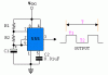
OK, for now I will use 555. The reason I changed to XTL and 4060 was to avoid frequency variations of the WIRE signal generator, also equal shape of the square wave. I at least knew the WIRE signal would stay the same.
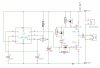
I wound lots of COILs when I was experimenting with them about a year ago, they all tended to be different (windings, thickness of wire, capacitors), They were in the hundreds of turns. As for length! I don't know. Once wound I would connect the capacitor, and unwind the COIL till it was tuned. I found the COIL winding a problem of frequency change as they settle after winding, I tried glueing the COILs then heatshrink to hold them. All tuned to 55930Hz.
I never thought I would be asked about them.
 
Not washing that Cat again!!!

As I said they tended to be different.

At the time I could understand mH, if I went back into it I'm

sure it would all come back to me.

Here are some notes I made:
5.395 mH-1500pF/6.23mH-1300pF/7.37mH-1100pF/8.10mH-

1000pF/9.00mH-900pF/10.15mH-800pF.

I used Ferrite tube cores of differnt sizes, like those on

USB cables, the size I found convenient is 5.2X 18.4.

If it is better for you to work out perhaps you can dictate

to me what you are asking for and I will make more coils to

that specification. I have 38swg copper wire.
 
If I use this configuration of 555 can it be tuned to 55930HZ?
 

Attachments

  • 555_circuit.GIF
    555_circuit.GIF
    3.3 KB · Views: 164
555

Sure. Make R2 a 10k pot so you can "tune" it.

For your amplifier add a pot (50K?) between the transistor amplifier and the input of the comparitor.
 

Attachments

  • 555.PNG
    555.PNG
    75.6 KB · Views: 159
Hi Ronv,

Thanks a lot.

I notice your 555 simulation is set to 50K, will it be ok for 55.930K that all of my COILs are tuned to? I want to keep everything uniform, so that it is interchangeable.
 
Hi Ronv,

Thanks a lot.

I notice your 555 simulation is set to 50K, will it be ok for 55.930K that all of my COILs are tuned to? I want to keep everything uniform, so that it is interchangeable.

If you put the pot in place of R2 you can adjust it for maximum output from the receiver.
 
I think your good to go. I guess I forgot to post-- You should also be able to put a pot between the output of your transistor amplifier and the comparitor to adjust the gain. maybe a 50k pot.
 
Hi Ronv,

If you get chance would you run your eye over my circuit (Attached) Especially the FET orientation.

I noticed a GND joined to 12V on your PNG, I didn't add this !?!?

Cheers.
 

Attachments

  • WIRE 555 FETS.jpg
    WIRE 555 FETS.jpg
    42.4 KB · Views: 180
  • 555.PNG
    555.PNG
    75.6 KB · Views: 151
Last edited:
If I had remembered to ground the battery it might have. :)
I'm surprised the timing is OK.
 
MMm that's interesting. So I presume the 'real' GND on the circuit also isn't connected.

What happens if you remove the offending GND and add a Battery GND, on your simulator?
 
Hi Ronv,

I made the circuit, lovely even square wave from the 555.

With NO WIRE connected, the PFET gets hot. This could be my circuit making skills!!! Or does it need a WIRE connected for the circuit to work properly?

I couldn't test it with a WIRE stretched out today.

Cheers.
 
With no wire they should be pretty cool. There is a little current during switching, but not much. You should see a 12 volt square wave at the output with or without the wire, but good to test without the wire first.
 
Status
Not open for further replies.

Latest threads

New Articles From Microcontroller Tips

Back
Top