Continue to Site

Welcome to our site!

Electro Tech is an online community (with over 170,000 members) who enjoy talking about and building electronic circuits, projects and gadgets. To participate you need to register. Registration is free. Click here to register now.

  • Welcome to our site! Electro Tech is an online community (with over 170,000 members) who enjoy talking about and building electronic circuits, projects and gadgets. To participate you need to register. Registration is free. Click here to register now.

Small signal to 5V output amp

Status
Not open for further replies.
Hi Ronv, A bit of feedback:
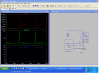
NFET WIRE SIG GEN.

Test on the bench with 2Xseries 15ohm resistors instead of WIRE. And 2X parallel Schottkys instead of suggested diode, to be

ordered soon. = even Square at D-pin, NFET cool, tot current Circuit + Resistors 200mA, Diodes cool, Resistors hot.

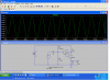
Test with Long WIRE 27ohm = only bottom of square wave at D-pin visible, NFET tepid, Tot circuit + WIRE 100mA, Diodes cool, WIRE cool.


COIL CIRCUIT, with long WIRE +NFET SIG GEN. COIL 100mm above WIRE.

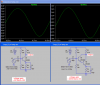
At Circuit output 100mV DC (Bit low I had hoped for up to 5V)

Using a spare COIL simply connected to Oscilloscope, COIL 100mm above WIRE = 50mV

So I'll do more tests, and check all of the COILs and Circuits.

Cheers.
 
Good, Just about there. Should be a nice square wave now and everything cool?
 
Your output should be about the same as the short wire was with the 555 driving it. Is it?
We should be able to increase it by adding another battery so that there is 24 volts going to the top of the wire. The 555 still needs to be at 12 volts. Lets see if this doubles the output.
 
Your output should be about the same as the short wire was with the 555 driving it. Is it?
We should be able to increase it by adding another battery so that there is 24 volts going to the top of the wire. The 555 still needs to be at 12 volts. Lets see if this doubles the output.

I prefer not to go on the 'more battery' direction if possible.

The first WIRE sig gen was a simple 555 with small cap, to the WIRE, and only used a small pack of penlight Batteries 7.5V. I did tests, but it was a long time ago. From memory, It worked fine on shorter WIREs. If I tried this 555 on the Long WIRE 27ohm, it might even give similar results to your circuit. Next week I will do some comparison tests.

I was puzzling about the first test I did on your circuit with the Diode incorrect. The square wave seemed to show only the 'bottom part of the wave', at the D pin, but there must have been some 12V part of the wave, for the COIL to 'see' How does this small 'top part of the wave' signal give a signal?

After the Diode correction, the wave looked strong at the D pin end of the long WIRE, but the picked up signal at the COIL was similar to before. On the long WIRE.

I have never tried the short WIRE on your circuit, as it would be too short. I have tried a medium 6ohm WIRE (Sorry to confuse) this showed a strong enough to use, signal at the COIL.

I think that if this is the strongest we can get with a 12V Battery, I will have to try other ideas.

I presume it is the combination of Voltage and Current drawn in the WIRE that gives the signal? What would happen if I wound a Transformer to give more Volt, less Amps?
 
Last edited:
I was puzzling about the first test I did on your circuit with the Diode incorrect. The square wave seemed to show only the 'bottom part of the wave', at the D pin, but there must have been some 12V part of the wave, for the COIL to 'see' How does this small 'top part of the wave' signal give a signal?
Without the diode the voltage due to the inductance of the wire makes the voltage go very high (few hundred volts) until the FET breaks down. There is still the same current flowing in the wire it's just not good for the FET. (see picture)

I have never tried the short WIRE on your circuit, as it would be too short. I have tried a medium 6ohm WIRE (Sorry to confuse) this showed a strong enough to use, signal at the COIL.

How high is it. This might be a good data point.

I think that if this is the strongest we can get with a 12V Battery, I will have to try other ideas.
I think we need some data and some ideas. Maybe you could make a plot of the coil output, the FET amplifier and detector output vs. distance. Then decide what range is required. We should also address how you plan to change the gain to keep the amplifiers from "clipping" once the input is high enough with the coil far away from the wire.
Is there something you can do with the micro to get the coil in range?

What would happen if I wound a Transformer to give more Volt, less Amps?

I think with a transformer we would need a different driver as this one has a DC component that the transformer wouldn't like.

The output with the long wire should have been 4X the 555 circuit with the short wire.
 

Attachments

  • wire diode.PNG
    wire diode.PNG
    69 KB · Views: 180
Last edited:
OK, The Diode is now correct.

Much depends on the whether I am indoors, or can stretch the longer WIREs out.
I have a short WIRE, and simple 555+cap Sig gen for indoors. I do simple tests, like Coil tuning, plus ideas I get that might improve things.

All of the shorter WIREs can be used with the various Sig Gens I have some with 'Volume' controls.

So I am really only thinking about getting the long WIRE working. I will probably have a dedicated Sig Gen for each WIRE. If this was done each WIRE Signal would be correct for your Amp circuit.

I have done many tests and readings in the past, and found there are many variables, so it is difficult to get clear readings. 1st the COILs seem to change (Temp or settling?)damp conditions on the WIRE etc.

The Opamp and Program will only work within the A/D range of 0-5V. I will only connect to it when the A/D input is usable.

I will try to get some usable data for you mid next week. From COIL to A/D output of your Amp circuit.

I get the impression that if everything was tuned correctly, and I accept a low A/D reading (say 0-1V) if it is smooth, It might work like that.
 
Last edited:
I did loads of tests today, but there is something happening that shouldn't, so the readings were all over the place.

It might be Gnd problems or COIL tuning. I'll have to have a look at how coils are made and tuned, again to see if I can get more stability.

Soon I will have better conditions to do tests, so I should be able to get more consistency.
 
Seems like it should be pretty sensitive as it is. The problem with adding amplification is that the signal input is almost as high as the power supply already (.2 to 10 volts). What kind of problems are you having? Maybe we can find another soultion.

Remembering past messages. Above and from others.

As I will probably have dedicated Sig Gens with each WIRE, and the long WIRE always has a weak signal, what would be the result of a little amplification from the Amp Circuit? Remembering it now has a Pot to control the input in case it's too high.
 
See if you can locate an LT1800 op amp and we can build an amplifier down to a mv. or 2.
 
OK actually an LT180X. If you can find the 4 to a package it would save .
 
OK actually an LT180X. If you can find the 4 to a package it would save .

Hi Ronv,

The LT 1800 is quite expensive, and I have to buy a minimum order to make it worth while. It looks like a good chip and I might think about it again later on.

So, I have been doing tests, especially with the long WIRE. I have been tweaking the COIL and changing components. The single NFET plus your Amp circuit now produces about 1/2 to 1V at the A/D on the PIC. I haven't had time to go further. This has to be done with a little care, in case of 'Smoke'

I think this might all work, if I dedicate each Sig GEN with Each WIRE.

As, with the long WIRE it could never over load the A/D, I wonder if 'say' a 2 to 3 X amplification on the COIL circuit would be better. Or does it simply X noise along with the signal, remembering that the COIL circuit has Pots to correct overload?

Cheers.
 
Last edited:
If it is that close maybe just another FET amplifier with a smaller capacitor (.01) across the 330 ohm instead of the 10 Ufd.

I was going for a gain of 100 or so.

If you have more than enough gain after adding the amplifier you can make the 1 meg at the input smaller and it will be more forgiving of the coil changing.

Do you mean design another Amp circuit? The problem is, that once I got the first one working some weeks ago, I sent the drawing to have the circuit made, I now have it plus the bill App 50 Dollars, and I fit the components. So for now this is too expensive.

So for the long WIRE we have The LM339 and LT1013 COIL Amp and the 1XFET WIRE circuit, maybe working. I think.

As for some gain, Audioguru said this many moons ago:

(((((You don't need to add Jfet circuits. The opamps are set to have a gain of 1. But by simply adding 2 resistors an opamp can have any amount of gain that you want.

The schematic is too small for me to show you how. )))))

So if he's correct, can I add resistors to the existing circuit?
 
=camerart;971298]Do you mean design another Amp circuit? The problem is, that once I got the first one working some weeks ago, I sent the drawing to have the circuit made, I now have it plus the bill App 50 Dollars, and I fit the components. So for now this is too expensive.

Sorry, Didn't know that.


As for some gain, Audioguru said this many moons ago:

(((((You don't need to add Jfet circuits. The opamps are set to have a gain of 1. But by simply adding 2 resistors an opamp can have any amount of gain that you want.

The schematic is too small for me to show you how. )))))

So if he's correct, can I add resistors to the existing circuit?

Many moons ago we were working with .1 volts minimum and 10 volts maximum - we didn't need any gain. now we are down to .01 volts to .05 volts.

Anyway, No we can't just add a couple of resistors. The fet amplifier has lots of current gain but little voltage gain. So maybe what we can do if you think you need more gain is switch the fet out with a darlington transistor. There will be some component changes but only one new resistor I think.
The 2 transistors in the simulation represent the darlington transistor. You can use something like a 2N6426 or another with a Hfe of 10,000 or so. You can adjust the gain by changing the cap in the emitter. Larger is higher gain, lower is lower gain.

Maybe you can post a schematic of what you have built?
 

Attachments

  • dar amp.PNG
    dar amp.PNG
    76.4 KB · Views: 181
Sorry, Didn't know that.


Many moons ago we were working with .1 volts minimum and 10 volts maximum - we didn't need any gain. now we are down to .01 volts to .05 volts.

Anyway, No we can't just add a couple of resistors. The fet amplifier has lots of current gain but little voltage gain. So maybe what we can do if you think you need more gain is switch the fet out with a darlington transistor. There will be some component changes but only one new resistor I think.
The 2 transistors in the simulation represent the darlington transistor. You can use something like a 2N6426 or another with a Hfe of 10,000 or so. You can adjust the gain by changing the cap in the emitter. Larger is higher gain, lower is lower gain.

Maybe you can post a schematic of what you have built?

The circuit I've built is as your suggestion #52. Then a 50K Pot was added between C3 and R1, in case of over load.

Many moons ago, I was trying to make a system that could cope with maybe a too wide range. The shorter WIREs are easy. We have been struggling trying to get the long WIRE working, and I have decided to have a dedicated SIG GEN for this WIRE, as it is working on the lower extreme of signal.

It seems that the long WIRE needs careful tuning, perhaps capacitance, I'm not sure.

From the tests earlier in the week, I think this set up will work. And if it needs a bit more amplification, I'll try your Darlington Pre amp.

I am keen to try it with the whole system, and it will be a little time while I program the new settings etc.

I'll let you know what happens, do I post here?

So for now, Cheers, and thank you very much.
 
So maybe what we can do if you think you need more gain is switch the fet out with a darlington transistor.
I know that a darlington has a very low input current so its input resistance is very high.
I simulated an ordinary transistor and a darlington that uses the same collector and emitter resistors. The gain of the darlington is half the gain of the ordinary transistor.
 

Attachments

  • ordinary vs darlington amplifier transistor.PNG
    ordinary vs darlington amplifier transistor.PNG
    35 KB · Views: 187
Status
Not open for further replies.

Latest threads

New Articles From Microcontroller Tips

Back
Top