Continue to Site

Welcome to our site!

Electro Tech is an online community (with over 170,000 members) who enjoy talking about and building electronic circuits, projects and gadgets. To participate you need to register. Registration is free. Click here to register now.

  • Welcome to our site! Electro Tech is an online community (with over 170,000 members) who enjoy talking about and building electronic circuits, projects and gadgets. To participate you need to register. Registration is free. Click here to register now.

Op Amp not working and overheat

flyingphoenix

New Member
Hi everyone,


I'm very new to electronics world and would like to build a basic non-inverting amplifier using the LM7171 BIN op-amp. My goal is to amplify a 1V DC input, and I'm using a simple feedback configuration: a fixed 1kΩ resistor from input to ground, and a 10kΩ potentiometer from output to the inverting input.

The problems are:


1. Output Doesn't Vary with Potentiometer
When I turn the potentiometer, the output doesn’t change — it stays at around 1V, matching the input. Only when I rotate the pot all the way to max (10kΩ) do I get an output of ~5V, which I assume is due to gain clipping (my supply is ±5V).
But I expected a gradual increase in gain/output as I adjusted the pot. For example, halfway (~5kΩ) should give a gain of 6 and ~6V output (before clipping), but it still reads only 1V.


2. Op-Amp Overheats at Higher Supply Voltages
When I increase the supply from ±5V to ±10V or ±15V, the op-amp gets very hot, even if there's no signal input.
I verified the power pins are correctly connected, and my soldering is clean — no bridges or shorts.
The datasheet says the LM7171 supports up to ±15V, so I’m not sure why this is happening.


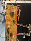
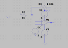
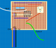
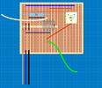
Please could anyone help me please? Attached you can find the circuit on a veroboard and also the schematic. Thanks!

Please ignore everything starting from the grey wire, they are a previous circuit that I already get rid of!
 

Attachments

  • schematic.png
    schematic.png
    44.1 KB · Views: 49
  • Image (1).jpg
    Image (1).jpg
    71.5 KB · Views: 50
  • schematic 2.png
    schematic 2.png
    14.7 KB · Views: 42
The negative end of the 1 V DC input must be grounded.

Note that when the circuit is working, it will not be able to operate at a gain of 10 because that would mean a 10 V output with only a 5 V rail.

ak
 
Hi,

Thanks for your reply. I did ground the 1V input. Sorry missed out this detail in the drawing.

However, someone pointed out I wired the potentiometer wrongly - i only needed two connections, but i did 3 wires conenction so it becomes a voltage divider instead hence why the output is 0/5 at extremes. Maybe this is the reason why (I will test this again tomorrow, hopefully this will fix everything)

And also, yes I do understand the output is limited by the rail supply, so when I increased the rail power supply to 10 V i could see the 10V output (gain of 10). However, this comes with the consqeuence of overheating the op amp. I've read some other posts with similar problems and suggested that it might an oscillation problem. I tried putting a 0.1 uF and 10uF capacitors to both V+ and GND as well as V- and GND but it doesnt help with the heating issue.

Would greatly appreciate any insights. Thanks again
 
The OpAmp should not overheat as you have no output load on it.

A complete schematic of pins and connections and power would be a good
idea for forum to help you with.

If you overheated, drew lots of current, you have wrong polarity or wrong connection
of one or more pins.
 
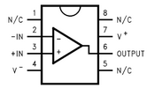
Hey this is the pins (from datasheet) and my connection. I made sure the -5V was connected to pin 4 and +5 connected to pin 7
It looks like what is happening is when you move the potentiometer all the way to left, it connects the output of the op-amp connected to the wiper (middle pin on pot) to ground (orange wire). So you are shorting the output to ground which is why it is overheating.
 
Hi everyone,


I'm very new to electronics world and would like to build a basic non-inverting amplifier using the LM7171 BIN op-amp. My goal is to amplify a 1V DC input, and I'm using a simple feedback configuration: a fixed 1kΩ resistor from input to ground, and a 10kΩ potentiometer from output to the inverting input.

The problems are:


1. Output Doesn't Vary with Potentiometer
When I turn the potentiometer, the output doesn’t change — it stays at around 1V, matching the input. Only when I rotate the pot all the way to max (10kΩ) do I get an output of ~5V, which I assume is due to gain clipping (my supply is ±5V).
But I expected a gradual increase in gain/output as I adjusted the pot. For example, halfway (~5kΩ) should give a gain of 6 and ~6V output (before clipping), but it still reads only 1V.


2. Op-Amp Overheats at Higher Supply Voltages
When I increase the supply from ±5V to ±10V or ±15V, the op-amp gets very hot, even if there's no signal input.
I verified the power pins are correctly connected, and my soldering is clean — no bridges or shorts.
The datasheet says the LM7171 supports up to ±15V, so I’m not sure why this is happening.


Please could anyone help me please? Attached you can find the circuit on a veroboard and also the schematic. Thanks!

Please ignore everything starting from the grey wire, they are a previous circuit that I already get rid of!
You can replace the Potentiometer and see if solves the problem.
 
To Galgso point, the OpAmp outputs has a short circuit current rating of 140 mA TYPICAL, so
if its was 200 mA and with your 5 V supply thats 1 watt, eg. hot to the touch.
 

New Articles From Microcontroller Tips

Back
Top