Continue to Site

Welcome to our site!

Electro Tech is an online community (with over 170,000 members) who enjoy talking about and building electronic circuits, projects and gadgets. To participate you need to register. Registration is free. Click here to register now.

  • Welcome to our site! Electro Tech is an online community (with over 170,000 members) who enjoy talking about and building electronic circuits, projects and gadgets. To participate you need to register. Registration is free. Click here to register now.

Small signal to 5V output amp

Status
Not open for further replies.
Hi Ronv,

I built the circuit. I used a Capacitor 103 instead of 0.006U. Is this ok.

The test Battery pack is 10.5V. The output at LM339 shows 9V App. If I remove the LM139 the voltage at the +input pin, with no signal is 20mV. If I add a typical signal through the Coil, it show 200+mV.

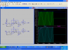
I have access to an Oscilloscope 1 day/week. If you wish to help me troubleshoot the circuit.
 
Hi Blueroomelectronics,

I used the Schematic from Ronv's message posted 4.Mar on page 2.

I used LT1013CP and have found a PDF showing an obsolete LT1013CP with different pin outs. I have just bought them from Farnell, so I doubt it is this.
 
I'm puzzled!

I contacted the supplier Farnell giving them the pin outs I used for the LT1013, and they said that was correct, but today I re-wired the circuit to the other set of pin outs and it seems to be working ok, on my first test.
 
Hi Ronv,

Your circuit works fine.

I had some difficulty due to there being 2 different Pin out configurations for the LT1013, I used the top one on the information PDF and should have used the other one.

Thank you.
 
The datasheet shows that each package type has different pins.
Didn't you look at the datasheet??
 
Hi Audioguru,

One of the bains of my life is a mild form of Dyslexia. This means that even though it might seem obvious to one person, it migh take 5 or 6 checks of a document or explanation before I get it. I usually get there in the end though.
 
Hi Ronv,

As I said before your circuit works ok.

However, would it be possible to make it more sensitive? The normal working WIRE signal is just a little weak. On the previous circuit, that I experimented on before your circuit, I added a 2N3819 in front of the Opamp, which seemed ok at first but because of the way the circuit was, it wasn't reliable ( suffered from collapse??). The output had a narrow range, where your circuit has the almost 0 to full voltage swing. So could I add a 2N3819, if so how?
 
Seems like it should be pretty sensitive as it is. The problem with adding amplification is that the signal input is almost as high as the power supply already (.2 to 10 volts). What kind of problems are you having? Maybe we can find another soultion.
 
Hi ronv,

I have attached the Circuit that nearly works, but not reliably. There have been constant modifications from the original circuit a year ago, some you can see.

The problems seem to be the large range of coil signal due to: Signal WIRE variations, and distance of coil to the WIRE. The main problem is low WIRE signal (I can control it somewhat, but once it's up to the highest level, this might still be too low if the coil is too far away...say 6 inches) The 2N3819 circuit was added that did the job, but caused the -IN pin on the LM324 to go below 0.3v making the internals collapsed.

With your circuit, it seems to me as an amateur, to be more robust. If it was possible to add a 2N3819 to the front of your circuit, as long as it doesn't cause damage, I think I could control the WIRE input to give the correct signal power.
 

Attachments

  • coil Schematic.jpg
    coil Schematic.jpg
    363.4 KB · Views: 200
I see that your signal frequency is high at 55kHz but your lousy old LM324 opamp works poorly above only 2kHz.
Replace the LM324 with an MC34074 quad opamp that has the same pins and also works with its input voltages very low. It works well up to 100kHz. Did you properly disable the unused opamp to prevent it from oscillating?

Get rid if the 10uF capacitor that short-circuits the output of the first opamp. Place the capacitor in parallel with the diodes at the input of that opamp if you need filtering.
 
Hi Audioguru,

Ok, I have almost given up on this circuit, but if you are correct, I'll of course do some tests.

I have built a test circuit sent from Ronv, I'll see how his ideas work, in parallel with yours.

Thanks.
 
Ok, I have almost given up on this circuit, but if you are correct, I'll of course do some tests.
The LM324 is an old low power opamp so it has problems with frequencies above only 2kHz.
An MC34074 quad opamp will have much more gain and a much higher max output in your circuit that operates at 55kHz.
 
I have only just received parts and built RONV's circuit from 'post #11', and for economical reasons need to leave a gap till my next order is economical.

At the moment I only need 4 circuits.

So for now I'll try Ronv's circuit, as I have all of the parts. Have you had a look at it?

I will also modify my existing 4 circuits, as you suggest then add some MC34074 chips later if needed.

Pity I didn't know about the LM324 problem. It might have saved me a lot of time and cost. Now I know!!

cheers.
 
Ronv's circuit in post #11 also uses modern fast opamps but has no voltage gain. Gain can easily be added.
 
Ok.

I'm glad these chips are ok, I could only get the surface mount chip, so I had to connect legs to each Pin then solder it into the normal socket for my test circuit, Fun Fun. If it works ok, I will then etch proper circuits.
I have built a test RONV circuit, and with the signal WIRE close to the COIL it shows a healthy 0V to 12V output swing. However in tests I have found that the COIL is sometimes too far from the WIRE, so the COIL input is perhaps around 50mV, and seems too low. If you look again at my circuit, the 2N3819 was added and this boosted the COIL input to the LM324 enough. I altered the WIRE circuit to be adjustable, so I could turn it down. So it nearly worked but as you say, perhaps because of the fast frequency failed.
 
So what I think I need is a way of adding a 2N3819 to the attached Circuit from Ronv to take the sensitivity from the 0.2mV input down to 0.05mV
 

Attachments

  • New coil circuit.PNG
    New coil circuit.PNG
    80.8 KB · Views: 173
You don't need to add Jfet circuits. The opamps are set to have a gain of 1. But by simply adding 2 resistors an opamp can have any amoumt of gain that you want.

The schematic is too small for me to show you how.
 
Hi camerart,
Here is the problem with adding gain. Your signal is from lets say 50 mv to 10 volts. With a 12 volt power supply the best we could do is 60 mv to 12 volts. The circuit works pretty well down to 50 mv. My guess is that you have to divide the output by 2 to be compatible with the a to d??? I suspect the problem is that the deadband in your micro is that big or it shuts down with no signal. So here a a few questions. Does the signal really go to 10 volts? Is the limit to the a to d 5 volts? Can you modify the code? Could you give some more details on the whole thing?
 
Status
Not open for further replies.

Latest threads

New Articles From Microcontroller Tips

Back
Top