Continue to Site

Welcome to our site!

Electro Tech is an online community (with over 170,000 members) who enjoy talking about and building electronic circuits, projects and gadgets. To participate you need to register. Registration is free. Click here to register now.

  • Welcome to our site! Electro Tech is an online community (with over 170,000 members) who enjoy talking about and building electronic circuits, projects and gadgets. To participate you need to register. Registration is free. Click here to register now.

Simple load cell circuit with Ins Amp output to arduino.

Status
Not open for further replies.

maxslo

New Member
Hello, long time lurker, first time poster here.

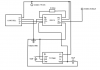
I would need your wisdom on a project that i'm working on.

I've created a circuit that should report the load on my load cell to the arduino, but i'm constantly getting a reading of 3,8V no matter if there is any load or none at all.

The load cell is working an all of the elements i've used are new or used but working, so that leads me to beleive i've messed up somewhere in the schematics.

Would really appreciate if anyone would be able to check the attached schematics and let me know what i should correct to make it work.

Thanks! :)
 

Attachments

  • Navor2.png
    Navor2.png
    17.2 KB · Views: 528
Two things jump out..

1) A 10ohm gain resister is going to get you 1:5000 gain... If the loadcell has @2mV/V then at 5v you have an output of 10mV If that is multiplied by your gain it will max out... Even 1mV will max out.. I use a 220 ohm...

2) I have also tried to power the -V with a 7660... No chance.... At best it gives -1V.. The current output at -5V is minimal and the ina114 wants 3mA...

This is how I do it
upload_2015-7-6_9-42-33.png

You get approximately 1.2V at the vref pin.... so no load is 1.2V and max load will be about 4.5V
 
Thanks i'll try to find a 220ohm resistor, the reason i've used 10ohm is that it's also been used here and i don't know what rating the loadcell has...

I'm a bit in a rush for this, if it will work with 7660 and 220ohm resistor i'll leave it be for a time, otherwise i'll look for the diodes. are they easy to come by in electronic stores?
 
Ok, i'll just dig them up from dead PSU's then, i have plenty of those laying around. Why do there need to be 2 diodes tho, wouldn't 1 work just the same?

That could be it, i don't have the load cell here so i'll be able to report back with the results tomorrow.
 
Ok, i've tested both without the sensor plugged in (I'll have access to it in the afternoon)...
with the 7660 circuit i've measured -4.75V on the V- pin
with two diodes, i've measured 0.8V on the REF pin
 
Yeah i know that, i've tried reading with both separately.
The 7660 actually does give almsot -5V to the V- Pin,
If i replace 7660 for the two diodes i have 0,8V on the REF Pin
 
The output with the cell on is still -4,8V
But still same problem, with the dual diode circuit or with 7660, i get around 0,8V on arduino analog input now, and again doesnt scale with load :/...

I'll create the schematics of the working circuit (wich i didnt use as it's connecting thru what looks like COM port to a LabView card that runs on a win 98 PC) and the whole point of this new circuit is to update the whole thing a bit.
 
Are you connecting the cell correctly??? Measure the bridge... A balanced bridge should measure the same across the EX as the Sig output.... Sig+ to Ex+ should be the same as Sig- to Ex+ same with the Ex -...
An unbalanced bridge usually has higher resistance on the Ex- than the Ex+, but still the readings from Sig+ to EX+ and Sig- to Ex+ will be the same....

When testing a balanced 350 ohm bridge.. There should be 262 ohm resistance on each leg.. ie sig to Ex.. Not 350 as you would think as the measurement has 1.050k in parallel with it... If you get 350 ohms, then one gauge is broken...

A 1k balanced bridge should measure 750 ohms on each leg....
 
I've measured the cell, there is 90Ohm resistance between all pins.

Also here is the schematic of the old working circuit..

EDIT:
the input is 12V not 5V
10uF capacitors are rated for 25V not 50V, my mistake there...

Navor Copy.png
 
Last edited:
I've not played around with load cells so I may be talking rubbish. I was looking at the difference between the schematic for the the design that was claimed to be working and the one in maxslo's original post. The only difference I can see is the one that is claimed to work has a resistor whose value can be adjusted between 33K and 38.5 K in parallel with one of the load cell resistors. The only effect I think this would have is to produce an offset on the output. This made me wonder if the non working version IS wired as shown in the schematic. I first suggest checking that pins 2 and 3 on the INA114 are both at + 2.5 volts with respect to 0 volts. (As the load cell is powered between 0 volts and +5 volts. Note the -Ve supply does not provide power to the load cell.) If pins 2 and 3 are a +2.5 volts then try unbalancing the bridge electrically by connecting a resistor (Say 33k) between 0 volts and either pin 2 or 3 an seeing if the output on pin 6 changes. This suggestion is based on the load not being applied correctly to the load cell with the scales dismantled. I suspect that the load needs to be applied via a bar passing through the slot in the load cell bar.

Les.
 
Status
Not open for further replies.

Latest threads

Back
Top