Hi all!
This is my first post here and I am looking for some assistances on how to wire the load cell for my scales. I'm guessing this is very basic stuff but it has me pretty stumped!
My load cell has 4 wires red, black, green and white. The display unit has 6 wires (red, black, green, white, blue and yellow)
The load cell and display were previously connected with what I believe were rs232 connectors. A number connections in the rs232 were broken when one of the connectors got crushed and destroyed.
I'm now tying to work out which wire should be connected to which!
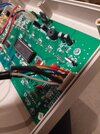
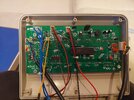
Can anyone assist me with how to proceed with this. I've looked online for wiring diagrams etc and found nothing. I took a picture of the connection in side the display unit showing the 6 wires connected to the board but I'm pretty much with stuck with where to go next.
Many thanks,
Andy


