Continue to Site

Welcome to our site!

Electro Tech is an online community (with over 170,000 members) who enjoy talking about and building electronic circuits, projects and gadgets. To participate you need to register. Registration is free. Click here to register now.

  • Welcome to our site! Electro Tech is an online community (with over 170,000 members) who enjoy talking about and building electronic circuits, projects and gadgets. To participate you need to register. Registration is free. Click here to register now.

Controlling multiple outlets with SSR Relay module and Arduino

nicofiaba

New Member
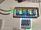
Hi everyone. For my "meat aging machine" project I need to turn on and off multiple devices remotely according to the value of temperature ad humidity read by a sensor. I want to make a power strip with 4 outlets. I want to control each of those with a solid state relay (I have a module of 4). Is it safe to wire it like I show in the figure below? The solid state relay module will be in a separate box and Arduino will be in a third box. My concern is about those 5V, GND and signal cables that go from the 220AC box, where the relay module is, to the 5V Arduino box. Is there any way to wire this more safely? Sorry for my ignorance, I'm here to ask you since I don't want to hurt myself. Thank you very much in advance.
 

Attachments

  • IMG_20240131_2308562.png
    IMG_20240131_2308562.png
    953.7 KB · Views: 123
There appears to be components marked LED1 etc. can you count how many connections they each have?

Mike.
Edit, not the LEDs but the little black object below it in your picture.
 
I'm hoping that it has opto isolators so the only connection is via light which normally come in a small black package.

Mike.
 
There are 4 of those black components below each led, one for every relay unit. Yes, wrong me. Is it okay to wire it like that and to send live to the relay and not neutral?
 
If it's the same as this one, that has slots between the control a power terminals on the relays, it does look reasonably well designed:

As Pommie pointed out, if the wiring is brown, blue & green (or green/yellow) the the live, which should be switched, is brown.

Add a fuse in the live feed to all the relays, rated at just over the total load current.

Make sure the whole relay module is securely mounted on insulating spacers so the end of the relay pins through the PCB are well clear of everything - 1/4" or 6mm at least.

And link the AC mains earth wire to the 0V (DC-) screw terminal, so if there is a fault it should blow the fuse rather than making the Arduino part live!

You could use the pin headers to connect the arduino, rather than the screw terminals - it's easier and safer as it allows the arduino to be quickly disconnected while you are working on it.
 
If it's the same as this one, that has slots between the control a power terminals on the relays, it does look reasonably well designed:
Do you mean those holes visible on the back of the PCB? I will check mine, but it looks exactly the same model.

Add a fuse in the live feed to all the relays, rated at just over the total load current.
Can you explain this please? What kind of fuse and where should I put it? Should I put it across the live wire before it splits in 4 wires in order to go to the relays?

And link the AC mains earth wire to the 0V (DC-) screw terminal, so if there is a fault it should blow the fuse rather than making the Arduino part live!
Is it safe to "mix up" the wires coming from mains to the direct current part of the relay module? I know earth wire is just a safety wire but I want to be sure that it will never carry any high AC current into the DC part of the circuit (Where is the fuse?)
Should I connect a piece of wire from the last screw terminal of the last outlet directly to the "DC-" screw terminal on the module? Or should I split the earth wire in 2 separate wires before connecting to the power strip and send one of them to the "DC-" terminal?

Thanks a lot for all your replies.
 
Have used those boards for years and they work well, provided you stay well under the 2 Amp rating for each channel.

You will see a Green resistor shaped component beside each SSR, that is a 2A fuse , so as metioned you could add a fuse in your mains supply input thats at least the sum of all of the SSR, so for you thats 8 amp or the next nearest higher value available.

You can also see just below those green Fuses is a black looking slot, its in fact a open area / hole in the pcb to physically isolate the mains part of the SSR and PCB from the DC input.

We are not qualified electricians, but would not put any mains wire, including Earth onto the DC side of that board.
Ours are wired almost as your original photo shows apart from the L and N colours being mixed up, though we pass Live though the SSRs , not Neutral.

Which type of board did your order a HIGH or LOW type ? High means you have to turn your Arduino pin High to turn ON the SSR, Low Means turning the Ardiino pin Low to turn ON the SSR.

If you are not competant with mains wiring then do get things checked out by a qualified electrician.
 
Do you mean those holes visible on the back of the PCB?
Yes, it shows they have at least considered proper isolation between the high voltage and control areas of the PCB.

What kind of fuse and where should I put it?
An eg. 5x20mm fuse with suitable holder, in series with the live wire before it splits to all the relay terminals.
It should be rated for at least 250V AC and appropriate current for the total of all the loads no more than 10A, lower if you can.

One for each relay live feed would be better still, a 2A or lower feeding to each relay.
(Edit - post above appeared while I was writing this - as the relay board already has individual fuses, just one one common one in line with the live feed to the board).

Should I connect a piece of wire from the last screw terminal of the last outlet directly to the "DC-" screw terminal on the module? Or should I split the earth wire in 2 separate wires before connecting to the power strip and send one of them to the "DC-" terminal?

I'd connect an extra earth wire where the incoming power cable connects to the first outlet, so you have three wires in that one earth terminal, if possible - the incoming one, the one that daisy-chains to the next outlet ground terminal, and one to link to the DC - terminal on the relay board.

That eliminates several terminals from the low voltage safety connection.
 
This board uses reliable OMRON optotriacs and adds a resistor style fuse for each 2A switch.

Your photo looks ok but beware that large area loops for line & neutral to each load will radiate more impulse noise on switching. So I recommend you use STP wire so each channel is shielded from secondary noise.
No need to connect earth cable to the DC- terminal on the relay module in your opinion? Can I rely to the fact that Arduino won't be connected to live in case a problem occurs? (I will never touch Arduino when the system is working though)
 
It was not for safety but noise immunity that I suggested STP cables for input. It depends on the dI/dt or dV/dt of your loads for parasitic EM coupling.
 
The Arduino is optically isolated from the loads (and power) being switched. There's no danger of shock from the Arduino board. There is a shock danger from the SSR board. The high voltage connections are exposed on the back of the board so it should be anchored down to prevent a shock when it starts to fall and without thinking you reach out to grab it.
 

Latest threads

New Articles From Microcontroller Tips

Back
Top