Continue to Site

Welcome to our site!

Electro Tech is an online community (with over 170,000 members) who enjoy talking about and building electronic circuits, projects and gadgets. To participate you need to register. Registration is free. Click here to register now.

  • Welcome to our site! Electro Tech is an online community (with over 170,000 members) who enjoy talking about and building electronic circuits, projects and gadgets. To participate you need to register. Registration is free. Click here to register now.

Samsung laser multifunction fixed. Error A1-4111

Status
Not open for further replies.
Add me to the growing list of thank yous. I am a computer tech, not a printer tech, and you saved me a ton of trouble.

Form one Mike to another, Thank You!!!
 
WOW! thank you it even worked on my Xpress C1810W printer. That little pad needed that little push which made all the difference. you saved me from purchasing another printer.
 
I am very grateful for the instructions on how to repair the actuator. I found that I had to do something slightly differently and I have attached a photos of what I found worked for me. I have two Samsung printers. On one they insisted on selling me a completely new actuator assembly (that I had to wait weeks for the assembly to arrive). With these instructions my C-3060 FW was back in operation in a half hour).


I found that on my C3060 FW that the pad wouldn’t move so I (after much trial and error) I removed the pad completely. I had some extra foot pads from some electronic equipment that were sticky on one side. I had to cut them to size to fit under the actuator arm. I also found out that the thickness was important. If they weren’t the correct thickness either the printer would endlessly cycle, or the print was washed out with sections missing. The tape method didn’t work for me. By trial and error, I thinned out the pads to the right thickness, stuck it on to the actuator and it worked well. I used forceps, scissors and a Phillips screwdriver to complete the repair.

Here are samples of the common self-stick footpads I used, significantly enlarged. Note their actual size is 11 x 3 mm not including the removable backing covering the sticky side.
I cut these down with scissors until they eventually were only slightly thicker than the original pad but still slightly larger so even if they shift they would still work as a stop (The thickness should end up 1 to 1.5 mm). I suggest one degrease their hands and fingers with alcohol before doing this so as not to ruin the glued side. The best way to do this is to remove the single screw holding the actuator arm in place so one can easily access the space under the arm.
120809


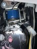
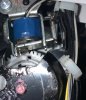
Here is the view of the actuator arm showing the single screw that should be removed to easily access the pads.

120810


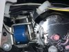
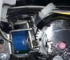
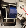
Here is a view of the new pad to the left and the original pad to the right of the actuator arm

120811


Red arrow new pad. Green arrow the original pad that did not need to be replaced. Note that I tried to closely match the thickness of the remaining pad.

I hope that this helps someone else to avoid unnecessary expense and lost time.

William Lipsky
 
Hello Pommie, can you look at the posted images from my Samsung and see if what adjustment it may call for to remove the error message? I did try to move the tape with a screwdriver but only succeeded in removing some tape glue at the top it didn't seem to have moved in the first place.
 

Attachments

  • samsung c1860fw 1.jpg
    samsung c1860fw 1.jpg
    252 KB · Views: 254
  • samsung c1860fw 2.jpg
    samsung c1860fw 2.jpg
    219.5 KB · Views: 242
  • samsung c1860fw 1.jpg
    samsung c1860fw 1.jpg
    353 KB · Views: 242
  • samsung c1860fw 2.jpg
    samsung c1860fw 2.jpg
    310.6 KB · Views: 250
Hello Mike, I have a different model machine, but did the new pad went on the inside (right-side of the image) of the inverted '' shaped metal or on the outside left- side)?
 

Attachments

  • image 1.png
    image 1.png
    285.6 KB · Views: 226
Apparently, your pad is slipping, You might try Scotch 90. Multiple coats. Dry till tacky between coats.
It's a spray adhesive. so spray on some sacrificial paper and apply wit a Q-tip. It's important to do the multiple coats and dry process.

Aside: I was using rubber cement for a christmas tree light hanger on a vinyl window using Nylon clips. The first one just used the foam 1573533483185.pngpads that were there. The second time used rubber cement with the pads removed and the nylon roughed up. The mounts got brittle.

I think about the third time, I got it right. Removed the foam adhesive. Last bits with methanol. Roughed the entire clip up. Primed the clip. Painted the clip with epoxy paint. Attached with Scotch 90. Did this over time (a few years) until all the clips were replaced.

1573533483185.png
 
Another resounding 'thank you'! Amazing that we the consumers let them get away with cludgy engineering like that......
 
Some engineer is probably employed to think up ways for the product to fail just after the Warranty period.

I did a lot of re-engineering at work when products failed. I had a motto that when I fixed them, I never wanted to see them again for the most part. Some of the electronics required maintenence like cleaning of slidewires in x-y recorders, cleaning of potentiometers, fans, lamp replacement, spilling of acetone on meter faces.

When stuff lasted about 7 years when it failed, they all had the same failures. Capacitors. I did a blanket replacement,

the environment for a vacuum guage was pretty crappy (moisture and heat) and usually the cap on the negative power supply rail failed and usually about every 5 years.

Sometimes you end up paying 3/4 to 1/2 the cost for repairs.

There were a few notable ones:
A Multi-channel-analyzer failed a few times near an SEM (Scanning Electron Microscope) and the schematics indicated no surge suppression at all. Manufacturer said, you exceed the 120 V 60 cycle power the unit is designed for. That's what the specifications are.
i fixed that.

Computers that we needed for measurements were dying and maintenance ability was going away. We had self-maintenance. I troubleshot down to the module level and we sent it back for a repair/exchange.

I added a OneAC, now Powervar power conditioner and an ISOBAR power conditioner and when a new upgraded computer system was installed, thonly failures were a floppy drive and cleaning of the cooling fan/inside. The SCSI hard drive was still operating after 17 years.

A power supply for an arc lamp died and when i looked at it, I found a 10A rectifier where a 50A or more rectifier should be. We had a good relationship with the manuafacturer and they re-engineered a new transformer and rectifier assembly and preformed the modification for free.
 
I took Mike's advice and stuck a piece of tape over the foam piece he identified and made sure the motor rotated freely during startup. Looks like that did the trick. Thank you!
 
Status
Not open for further replies.

Latest threads

New Articles From Microcontroller Tips

Back
Top