Electro Tech is an online community (with over 170,000 members) who enjoy talking about and building electronic circuits, projects and gadgets. To participate you need to register. Registration is free. Click here to register now.
Welcome to our site! Electro Tech is an online community (with over 170,000 members) who enjoy talking about and building electronic circuits, projects and gadgets. To participate you need to register. Registration is free. Click here to register now.
i never opened a UPS, but i guess must have a pair of huge capacitors for filtering and storing the power. To discharge them connect them with 10Ohm >10W resistor and will do the job....That's an idea to proceed
Factory built devices have to have a way that they will automatically discharge the capacitors in the system so I wouldn't worry about it too much. If its been turned off and unplugged with the battery removed for more than 15 minutes you are safe.
Before you canibalize it for parts, have you tested hooking good batteries to it ?
That is mostly what fails in UPSs. And you would be disabling what many people is after, a huge DC to AC inverter. I use one in my car for 115VAC on board.
Before you canibalize it for parts, have you tested hooking good batteries to it ?
That is mostly what fails in UPSs. And you would be disabling what many people is after, a huge DC to AC inverter. I use one in my car for 115VAC on board.
They are likely the main power transformers that step up the lower voltage up to the higher line voltage. They will have the primary's as the low voltage and the secondaries as the high voltage. But typically you can reverse them if needed to make a linear power supply out of them. and being UPS transformers they will have a high surge capacity.
However most UPS units have smaller transformers than they are rated for output wise. Their duty cycle is limited by the battery capacity so they dont need to be continuously rated at their maximum capacity. Many can only hold their maximum rated outputs for a few minutes and typically can only do about half there maximum rating as continuous duty units.
Also if used as step down transformers their outputs will be much lower than what the DC drive voltage was. Being a 24 V system they will likely only have about half that as an AC output. To maintain the steady line voltage as a backup power supply the use a sort of PWM method to keep the line voltage constant even though the battery voltages drop off rather fast.
Their windings ratios typically are closer to being what the battery's lowest working voltage is and then having that stepped up to the peak voltage of the output wave form. Hence the lower output voltage when used as a step down transformer.
Got a picture available. It would help with explaining what you have.
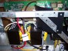
The weird thing about it, is what appears to be the primar winding is connected to the heatsink(a sheet of metal) that the voltage regulators are connect to.
This is an old version of UPS. The two transformers are 60 Hz (or 50 Hz if Europe) which are good to salvage. You may find some rectifier diodes used for charging mode. There will be some power transistors, likely MOSFET's used for and H-bridge for generating the modified sinewave. The rest of the electronics if for sensing of A.C. and charging control. You may find a 24v DC power relay for making the AC crossover from mains to UPS output.
New version UPS's use high frequency switching circuitry for DC boost. They are much lighter weight as they use small high frequency ferrite transformers.
I have very similar transformers from a UPS. You say they are for the output side, as in, take the 24V modified sine wave in, and transform it to mains level? Thus it would be possible to use them in reverse for very high rated linear supplies, taking 120V wall in and 24V out?
I had always figured they were input transformers for taking the 120V wall down to battery level for charging, but it makes much more sense that they are outputs. The UPS I scavenged them from was something like 3000VA, so they are massive transformers.
As far as discharging the caps - look at the capacitance rating on them. It is probably in the 1000's of microfarads. Just pick a resistor that won't dissipate them too fast, but not too slow either. And make it a high enough power resistor. 1kohm, 10W for safety, or the 10ohm 10W suggestion made before, depending on size and voltage of the caps. They should be discharged quite a bit by the time you get to them.
This is an old version of UPS. The two transformers are 60 Hz (or 50 Hz if Europe) which are good to salvage. You may find some rectifier diodes used for charging mode. There will be some power transistors, likely MOSFET's used for and H-bridge for generating the modified sinewave. The rest of the electronics if for sensing of A.C. and charging control. You may find a 24v DC power relay for making the AC crossover from mains to UPS output.
New version UPS's use high frequency switching circuitry for DC boost. They are much lighter weight as they use small high frequency ferrite transformers.
They are used in a step up application here. But technically transformers are bidirectional. If you apply line voltage to what was the output it them becomes a step down transformer.
Most likely they have the leads attached to the heat sinks because of the type of switching system they use. Its normal in many UPS designs.
I think it should work just fine but be aware that your output voltages will be lower than what they originally used as an input voltage when used in the inverter.
But being designed for inverter use your going to have some super reserve capacity if you need to ever overload them!
This site uses cookies to help personalise content, tailor your experience and to keep you logged in if you register.
By continuing to use this site, you are consenting to our use of cookies.

 I use one in my car for 115VAC on board.