Continue to Site

Welcome to our site!

Electro Tech is an online community (with over 170,000 members) who enjoy talking about and building electronic circuits, projects and gadgets. To participate you need to register. Registration is free. Click here to register now.

  • Welcome to our site! Electro Tech is an online community (with over 170,000 members) who enjoy talking about and building electronic circuits, projects and gadgets. To participate you need to register. Registration is free. Click here to register now.

Road to success (in hobby electronics)

Status
Not open for further replies.

hugoender

New Member
I just started building circuits as a hobby and so I thought I'd post some pictures of my circuits as well as my current work area (equipment). Here ya go. Feel free to comment on w/e you want (positive or negative comments).

Description of pictures (from left to right):
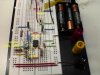
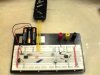
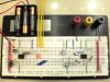
1. Here is my breadboard with my analog LED blinker circuit on the right (555 timer IC) and my digital LED blinker circuit on the left (12F509 PIC). Inbetween you can see the area where I program the PIC (where there are wires connected to nothing). You can see the PICkit2 programmer.

2. Here is the same breadboard close up.

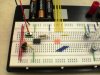
3. Here is a close up of the analog LED blinker. Using a 555 timer IC in astable mode. I have two potentiometers to control the frequency of the blinking LED and the brightness.

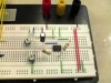
4. This is my digital version of the LED blinker circuit. I used at 12F509 PIC. To the right of the PIC you can see some wire that do not appear to connect to anything. This is the area where I program the PIC.

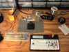
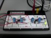
5. This is my stereo audio amplifier using two LM386 IC's. The gain is controlled with the two potentiometers (one for each channel) and the green LED indicates power on. I built this to amplify the sound coming out of my speakers at work. I had to small speakers connected directly to the computer and at max volume (on the computer) you could barely hear the music. This circuit did the trick and now I can blast my music :D

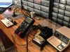
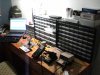
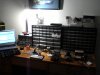
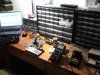
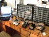
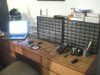
6. This is my work area. Not much yet since I am still waiting on some packages to arrive (soldering station, helping hands, etc.). I did however splurge on Akro-Mils storage cabinets :)

All these pictures were taken with my Sony Ericsson S710a Camera Phone.
 

Attachments

  • Breadboard1.JPG
    Breadboard1.JPG
    687.9 KB · Views: 372
  • Breadboard2.JPG
    Breadboard2.JPG
    696 KB · Views: 353
  • Analog Blinker.JPG
    Analog Blinker.JPG
    631.3 KB · Views: 355
  • Digital Blinker.JPG
    Digital Blinker.JPG
    644.8 KB · Views: 335
  • Audio Amplifier.JPG
    Audio Amplifier.JPG
    504.4 KB · Views: 353
  • Work Area.JPG
    Work Area.JPG
    742.8 KB · Views: 429
Last edited:
I have the same drawers. 0.5" x 1.75" labels fit the lower section of the drawer fronts perfectly and you can fit 3 lines of 9 point Arial font writing on each. I think the label sheets are Avery 5167 and have about 100 labels per sheet. I use them to label all my drawers. Any decent word processing software should have the label template in the letters and mailings section.
 
Hi hugoender

your work bench is pretty organised

still some advise

try to hang your storage on the wall a bit higher than you work bench
you will use the space under it
your work bench at this time look a bit small from the wall point of view

also an extra spot light/lamp is very handy to have

Robert-Jan
 
Thank you for the advice rjvh. I have indeed thought of these things but there is not much I can do for now. I cannot hang the storage drawers up on the wall because it is my room and I cannot start messing up the walls with holes or sticky stuff (it is my mother's house). The table is indeed narrow and there is not much space but it is the only place I have. Mind you, before now, this table was full of random stuff that wasn't even mine (stuff my mom put there like framed pictures and old books, etc. There was no place to even write on a small post-it! When I decided to start making circuits at home I grabbed all this stuff and placed it very neatly on the floor of my room and told my mom "This stuff does not belong in my room... it isn't even mine. Please put it somewhere else" and so she did :) I was very surprised and how easy it was.

As far as the lighting... yea it is terrible. But for now it will have to do. I have a small usb powered LED light connected to my laptop that I use for spot lighting but I will eventually have to get some sort of light source on this side of the room. For now I mostly work during the day.

@speakerguy: thanks for the suggestion. I will definitely try those labels out. For now I have been cutting out the part names and descriptions from the invoices with which they come with and taping those on to the small drawers. I am very lazy and the thought of having to buy labels, make a document with all the names and information, print it out, and paste them onto the drawers just seems like too much work right now. I will eventually do it... just waiting for all my materials to arrive in the mail so I can do it all in one sweep.
 
hi hugo,
If you cant follow R-J's hanging method, make a simple free standing shelf and put the component drawers on the shelf.

Two pieces of 9 inch by 9 inch wood for the uprights and a long piece just short of the bench width.
A central upright for the shelf if needed.

Add a 9 inch strip of plywood or fibre board to the back of the shelf to stiffen it up
and to stop bits falling off the back of the work bench.
 
Last edited:
Here is my latest circuit... a TV Jammer! I was EXTREMELY surprised when it worked the first time! :D (I did have to tune it with the 10k pot but once I found the right spot... it worked flawlessly). The only downside is that it only had a range of about 1ft. This is probably because I was powering it with 4V (the batteries are running low) when it should be powered with 9V. That, and I don't think I have the right IR LED for the job.
 

Attachments

  • TV Jammer2_rev.JPG
    TV Jammer2_rev.JPG
    155.2 KB · Views: 425
Edit: It is not a TV Jammer.... it is a TV Remote Jammer. Sorry for leaving out the "Remote" aspect of it.

I got the schematic for this from a website but after looking at it for a while I realized that, although it does work, the person that made this was not that good. There is a lot of stuff that is not needed, not to mention the values they have make the signal very weak. I just finished three different schematics for this same jammer and will implement them on my breadboard and see what happens. Two of my schematics don't even require the transistor and all three do not use the diodes (1N4148).
 
Nice work.

What's the link to the schematic you used?


Torben
 
Well I just received my last two packages and I am so happy. It is like Christmas right now :D

I got my soldering iron, helping hands, 300+ resistors, 300+ caps, 300+ diodes, 300+ transistors, 900+ leds... you name it and if it is something general... chances are i've got it :)

I did my first soldering job at home today soldering a ribbon cable to headers to connect my PICkit2 to the breadboard. I also changed my work area a bit (added a light). It is pretty late and I have work tomorrow so I will post pictures when I get a chance.


Nice work.

What's the link to the schematic you used?


Torben

I got the schematic/idea from TV Remote Jammer! - Instructables - DIY, How To, tech, offbeat but I strongly suggest you don't use their schematic. It is very wasteful and unnecessarily complex. As soon as I am able to build my version of it (without diodes or transistor), I will post pictures and schematic on here. Unless it doesn't work, in which case i will hide my tail between my legs.
 
Sounds like you ordered one of those Digikey multi pack grab bags. Cool eh?

What I do not understand is, why would you want to jam your remote? Is it one of those just because things.

900 LED's ??? hehe
 
Last edited:
Sounds like you ordered one of those Digikey multi pack grab bags. Cool eh?

What I do not understand is, why would you want to jam your remote? Is it one of those just because things.

900 LED's ??? hehe

It is a "just because" thing as well as a "OMG I made a device that actually controls/interacts with a commercial device!" thing as well as a "I want to watch the Discover/History Channel but my girlfriend doesn't and so she takes the remote from my hand and changes the channel but now with this she can't" thing :)

And yes... 900 LED's is amazing :D Never again will I have to triple check to make sure that the circuit I made will not blow my LED.

Actually, the bags of LED's were from Circuitspecialists.com and my resistors, transistors, capacitors, and diodes were from the very sketchy site of Futurlec.com.

I will say this though... although Futurlec.com has horrible reviews... they have been awesome with me. I have emailed them while my order was being processed and they have replied within the day. They have informed me when my order was delayed because of an out-of-stock item and told me how many days it would be before they had it in-stock (they said 2-3 days and it was actually 1 day). I do however, pay for the express shipping ($16 as opposed to the $4 for regular super slow delivery). With this shipping, I order my stuff, it takes about 2-3 days for them to get my order together and ship, and then it takes 2-3 days to receive all the items in the mail (properly labeled in individual bags and everything!). I have ordered from them twice and I have zero complaints.

One thing I do recommend is using paypal with them. Like I said, they are sketchy and I would not trust my credit card info with them.
 
Last edited:
Well I received my last packages and here is my setup now.

You can see right by my computer there is a case with tools (blue tools, pliers)... I got them free with my order from CircuitSpecialists.com :)

Also in the pics are my breadboard, multimeter, soldering iron with stand, glue gun, helping hands with magnifying glass, and two open drawers with 600 green and red LED's.
 

Attachments

  • Work Area 2.JPG
    Work Area 2.JPG
    378.7 KB · Views: 300
  • Work Area 3.JPG
    Work Area 3.JPG
    262.1 KB · Views: 293
  • Work Area 4.JPG
    Work Area 4.JPG
    201.1 KB · Views: 279
  • Work Area 5.JPG
    Work Area 5.JPG
    260.1 KB · Views: 280
  • Work Area 6.JPG
    Work Area 6.JPG
    333.6 KB · Views: 284
  • Work Area 7.JPG
    Work Area 7.JPG
    369.7 KB · Views: 302
That desk is nice and long but doesn't look too deep, should move your bits boxes as far to either end as you can, give yourself a little elbow room there in the middle to really work in. I did notice one thing that you need to rectify immediately! start labeling those bins!
Nice breadboards by the way, most people go with the tangled rats nest approach to breadboard building =) (You may too one day) Gotta build that stereo amp on perfboard now free up a breadboard and probably get a little better sound, that'll give you some good point to point soldering practice.
 
That desk is nice and long but doesn't look too deep, should move your bits boxes as far to either end as you can, give yourself a little elbow room there in the middle to really work in.

Your observation about the table not being deep is indeed correct. But there is nothing I can do about it. Moving the cabinets to the sides won't help much since they really are not taking up that much space. I move the table forward and have the cabinets on the edge of the table with their backs leaning against the wall so they don't fall behind the table. Therefore, the cabinets are really only taking up about an inch or so of space.

I did notice one thing that you need to rectify immediately! start labeling those bins!

Everything in my bins is in a bag that is labeled so no need to worry! I will label the bins but have not had time to sit down and do it (not to mention I am not quite sure how I am going to organize everything since I really do not have enough space :rolleyes:

All of thise bins you see are completely fully and I still have two bags worth of diodes, resistors, and transistors that I have stored somewhere else temporarily. I will probably place the dividers in each bin and have two values per bin. Maybe then everything will fit (otherwise I will have to buy another Akro-Mils 64 :D).

Nice breadboards by the way, most people go with the tangled rats nest approach to breadboard building =) (You may too one day) Gotta build that stereo amp on perfboard now free up a breadboard and probably get a little better sound, that'll give you some good point to point soldering practice.

Yeah I have been meaning to put my audio amp on perfboard (and I already have everything I need to do it), but I haven't done it because I want to improve the design so I can actually use it and not just have something that I will not use because it has too much noise. To be honest, I made the audio amp out of necessity at work and now I don't need it anymore so come to think of it, I might never put it on a perfboard. I think the first thing I will make permanent will be my TV remote jammer since it is small, simple, and I have already made it as efficient and functional as I see possible.
 
When I use a normal table as an electronics or computer desk I place a door on top of the original top.

You can often buy hollow core doors with one bad side at a reduced price. I put a few coats of polyurethane on the door.
 
When I use a normal table as an electronics or computer desk I place a door on top of the original top.

You can often buy hollow core doors with one bad side at a reduced price. I put a few coats of polyurethane on the door.

Oh wow... never thought of that... but it's too much work. I am fine with the space I have. Besides, soon enough grad school will start and I will have to move all of this stuff to my apartment. Hopefully there I will have a huge table!
 
Status
Not open for further replies.

Latest threads

Back
Top