@Mikebits
Did you get the mini or the micro mill? If you have the micro, here are a few suggestions:
Oops, your right JP, the first link was for a mini mill. I have the micro mill from HF.
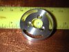
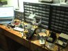
1) Get a set of MT2 collets. Eventually you will need clearance under the head. Alternatively, and a lot more expensive, a collet chuck with self-releasing E-series collets will work.
I have three. See photo.
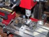
2) Do not trust the fine downfeed for precise work. Rig a cheap dial indicator to the spindle housing (non-rotating part) and use that for setting depth of cut.
In my to do list.
3) I always lock the spindle after adjustment before milling.
I do this as well.
4) I have disassembled two units and there is quite a lack of QC on the gibbs. You might want to check the gibbs, be sure they are flat and re-install.
The stock gibbs are bad. Can't remember where now, but I ordered a after market set from the net somewhere.
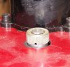
I made this mounting ring for an electric model last winter on my micro-mill. The counterbored holes is where I learned not to trust the fine feed. They are a little too deep.
John

")