Continue to Site

Welcome to our site!

Electro Tech is an online community (with over 170,000 members) who enjoy talking about and building electronic circuits, projects and gadgets. To participate you need to register. Registration is free. Click here to register now.

  • Welcome to our site! Electro Tech is an online community (with over 170,000 members) who enjoy talking about and building electronic circuits, projects and gadgets. To participate you need to register. Registration is free. Click here to register now.

Road to success (in hobby electronics)

Status
Not open for further replies.
Stack the two bit bins on top of each other. That will free up a couple of square feet. I think you underestimate the comfort factor of working in such a narrow wide space. It allows you to keep things you need close and things you need but don't need instant access to further back.
 
Stack the two bit bins on top of each other. That will free up a couple of square feet. I think you underestimate the comfort factor of working in such a narrow wide space. It allows you to keep things you need close and things you need but don't need instant access to further back.

I don't think you understand me... take a look at the last set of pictures I posted and look at the one that is "work area 3". If you look at the bottom right corner of the picture, you will see that the bins are at the very edge of the table with a big gap under them. The only thing keeping them from falling is the wall. If I place one bin on top of the other, all that will do is open up about an inch of table space and a huge gap between the table and the wall (where stuff can fall and never be seen again). Another reason I do not stack them is because then I would have to stand up to get something from the top bin. As it is right now, I can access all the drawers from where I sit without having to stand up.

Thank you for your feedback on my setup though. It is much appreciated. I just need a new table... period.
 
Woot! I just got a Fluke 73 True RMS DMM :)

Turns out a friend had one lying around and gave it to me. Everything works perfectly except for the screen which is slightly off contrast. You have to look at it at an angle for the numbers to appear perfectly dark and solid. You can still read it straight on though. I am very excited :D 
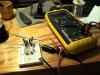
With it I also got some modular cables that you can plug into the DMM on one end and then plug the other end to anything else (banana plug cable, probes, etc.). The wire kit brings probes, alligator clips, some other clips that I have no idea what they are for (i think you screw them on to something), and the red and black modular cables.

I also received the Morgan logic probe kit from phanderson (PIC12C508 - Logic Probe) and put it together. Now I just need to test it.

This weekend I will get my girlfriend to print labels for my drawers :)\

Edit: Does anyone know if I can remove the code from the PIC12C508 that comes in the logic probe kit from phanderson? Or is it secured? I would like to know so I can extract it, save it on my laptop, and transfer it over to another PIC12C508 incase the one in the kit dies or gets messed up somehow.
 
Last edited:
if you need more breadbords i rocoment sure electronics i got mine from there and they are realy good and 5 breadbords and 500 jumpwires for £15 is a good price

**broken link removed**

each board is seprate and has screw mounting holes and the jumpwires slide easily into the holes
 
Last edited:
You can get them in the US from Mouser. The price is right and shipping is fast.

Mouser #: 589-TW-E40-1020
Mfr. #: TW-E40-1020
Desc.: Solderless Breadboards 630 + 200 Tie Points
$6.99 each

The are the nice ones with the blue and red lines next to the power buses.

The neat (not a mess) way to wire board is to cut the wires to the lenght. Precut wires make little sense. Order the wire by the spool or if you are cheap pull it out of cat5.
 
The neat (not a mess) way to wire board is to cut the wires to the lenght. Precut wires make little sense. Order the wire by the spool or if you are cheap pull it out of cat5.

I have a wire jumper set (as you can see from my album pictures) but those take longer to put on and take off than regular long wires. The reason I wanted those jumper wires was because they are easy to insert and remove. Once I am done prototyping and want to take a picture or something, then I would put the wires I have now.

And I am way ahead of you... I already have a bunch of CAT5 cable that I have cut up to use for wire :D

The reason I wanted to order from Sure Electronics is because they have great prices on a lot of things. Not to mention they have bags of components (for example 40 resistors of each value from 1ohm to 10Mohm) very cheap. My cart had 10 items totalling $78 but with that shipping price...I think I will hold off.
 
Last edited:
Well I did it... here is my dual power supply (positive and negative voltage source)

And you can see my handy dandy Fluke DMM :D

Edit: my circuit looks like the X-Wing from star-wars lol
 

Attachments

  • Dual PS.JPG
    Dual PS.JPG
    193.9 KB · Views: 308
  • Dual PS2.JPG
    Dual PS2.JPG
    209 KB · Views: 268
  • Dual PS5.JPG
    Dual PS5.JPG
    196.8 KB · Views: 268
  • Dual PS6.JPG
    Dual PS6.JPG
    265.9 KB · Views: 287
  • Dual PS Voltage.JPG
    Dual PS Voltage.JPG
    176 KB · Views: 273
Last edited:
Well I did it... here is my dual power supply (positive and negative voltage source)

And you can see my handy dandy Fluke DMM :D

Edit: my circuit looks like the X-Wing from star-wars lol

Good going. I think you posted this in the wrong thread though. ;)


Torben
 
Even though it's a true RMS meter, make sure you keep within it's frequency range. A switch mode supply could easily distort the RMS reading out of specs if the switching frequency isn't within the meters range. This is especially true of square waves as a decent amount of the voltage/current the device is carrying could be outside the frequency range the meter is sensitive to. A square wave with a rise time of 1us has a frequency maximum of 1mhz even if the square waves frequency is only 1khz.
 
Even though it's a true RMS meter, make sure you keep within it's frequency range. A switch mode supply could easily distort the RMS reading out of specs if the switching frequency isn't within the meters range. This is especially true of square waves as a decent amount of the voltage/current the device is carrying could be outside the frequency range the meter is sensitive to. A square wave with a rise time of 1us has a frequency maximum of 1mhz even if the square waves frequency is only 1khz.

lol not really sure what you said here. Can I damage my DMM if I go outside it's frequency range? I don't think I can but just want to make sure since what you posted is way beyond my level of understanding at this point :)
 
And here is my logic probe (the small breadboard on the right with the red LED).

On the left is the PIC12F509 that I programmed to blink the yellow LED and on the right is Morgan's Logic Probe. As you can see, the logic probe's red LED flashes at the same rate as the yellow.

Now that I know it works... it is time to commit it to a permanent board :)
 

Attachments

  • LED Blinker and Logic Probe.JPG
    LED Blinker and Logic Probe.JPG
    221.1 KB · Views: 381
  • LED Blinker and Logic Probe 2.JPG
    LED Blinker and Logic Probe 2.JPG
    224.6 KB · Views: 282
  • LED Blinker and Logic Probe 3.JPG
    LED Blinker and Logic Probe 3.JPG
    230.6 KB · Views: 362
Last edited:
:: Drum Roll ::

TA-DA! My first permanent circuit! This is the Morgan Logic probe and I soldered it onto a stripboard. It has a green wire with a pin header (male) as the probe. The board has two male pin headers for ground and 5V. You can see in one of the pics the soldering work and the cut copper traces. :)

Btw, you guys notice how much I have done today!? You know why? Because my girlfriend went to a concert and then a birthday party, so I have this whole night to myself to play with my "micrometer and little capacitors" as my girlfriend likes to say :D
 

Attachments

  • Logic Probe.JPG
    Logic Probe.JPG
    198.3 KB · Views: 285
  • Logic Probe 2.JPG
    Logic Probe 2.JPG
    153 KB · Views: 288
  • Logic Probe 3.JPG
    Logic Probe 3.JPG
    184.9 KB · Views: 283
  • Logic Probe 6.JPG
    Logic Probe 6.JPG
    172.4 KB · Views: 275
Last edited:
Status
Not open for further replies.

Latest threads

Back
Top