Continue to Site

Welcome to our site!

Electro Tech is an online community (with over 170,000 members) who enjoy talking about and building electronic circuits, projects and gadgets. To participate you need to register. Registration is free. Click here to register now.

  • Welcome to our site! Electro Tech is an online community (with over 170,000 members) who enjoy talking about and building electronic circuits, projects and gadgets. To participate you need to register. Registration is free. Click here to register now.

RL circuit practice

Status
Not open for further replies.
don't assume your page is the same size as mine

I prefer an RLC meter which uses a CC source to measure impedance at a chosen frequency to measure Rs, L, Rp, C, Q, d.f.

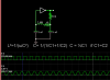
But when you have a reference capacitor to resonate in a suitable range, you can use a counter to measure the inductance regardless of DCR.

Here's is my interactive simulation where you can change L, DCR and C (7uF) ref
Try here

It is not that expensive to buy a 1% Reference Film Cap
1pc <$1
https://www.digikey.com/product-search/en?pv3=1&FV=fff40002,fff80010&k=cap+1%&mnonly=0&newproducts=0&ColumnSort=0&page=1&quantity=0&ptm=0&fid=0&pageSize=25

Not a real lab reference standard, but 1% for only a dollar, it's a good deal. Looks like I will have to look into the Falstad circuit simulator. I read about it a little. Appears to have neat features. Price is right, too.

Ratch
 
I'll post the result today, hopefully.


Thanks for reminding me.
Since the DC resistance of the coil is so close to the value of the test resister, perhaps you should use 15 ohms for the test resistor so that you can bring the absolute value of the coil impedance up to that value when you equate the voltages. Otherwise, select a somewhat low fixed frequency and adjust a potentiometer to get a balance. Then read the value of the pot.

Ratch

Seeing I am becoming Pedantic too...it's called a Resistor....not a resister...

Just thought I should share that.

tv
 
Seeing I am becoming Pedantic too...it's called a Resistor....not a resister...

Just thought I should share that.

tv
Further in the same sentence, the word is spelled correctly. Everyone makes typos, so don't waste time correcting them unless the typos make the statement or formula wrong. By the way, "pedantic" and "resistor" are not usually capitalized within a sentence.

Ratch
 
Inductor DCR = 12.5 ohm
Test load = 17.5 ohm
f = 2.37 kHz

1mH-17.5o-2.37kH-real.png


I had to use discrete resistors (in parallel) to achive 17,5 ohms, because my pot failed to achieve values in between 1-50 ohms (suddenly drops from around 50 ohms to short; need to get better pots). This is why frequency is not 2kHz.

sqrt((17.5^2 - 12.5^2)/(2*pi*2.37e3)) = 0.1 H

Doesn't seem to be right. Inductance would be two orders of magnitude higher than expected.
 
The denominator for your formula on the image should be (2*pi*f)^2 , not 2*pi*f . The calculations are correct, however. It should not matter if current driven or voltage driven as long as the DV's are equal across the components. If the AC resistance is significant and not taken into consideration, then the value of L will be calculated higher than it should be. It might explain why your L value at the higher frequency is higher. That is why I would like to keep the frequency as low as practical.

Ratch
Rachit , please review your comment and correct it. in #76
My formula has never been wrong and was shown correctly on the images in #75 and elsewhere

Now Elrion is using it.

Z(f)= R+jX(f)

for inductor , Z(f) = Rs +j2πfL
for series Rs or DCR

Using Pythagoras for a right angle triangle with equal current flowing thru both components at equal voltage drop and reading f.
upload_2015-12-29_15-37-38.png

DCR² + (2πfL)²= (R load)²
solving for L , the correct result was given as

L = sqrt (R load² - DCR²) /2π f

You incorrectly stated in #76
[QUOTE="Ratchit,The denominator for your formula on the image should be (2*pi*f)^2 , not 2*pi*f .[/QUOTE]
your mistake, not mine.

Thus with @Elrion 's new values
his calculated L should be
sqrt(sqr(17.5) - sqr(12.5)) / (2 * 3.1416 * 2370) = 0.82mH or about -18% low of nominal

edit...
I still think this method has problems
Use a highest f you have well below SRF (>1MHz) match R compute L then DCR error has less effect with large load R.

In this post I showed from HP (Agilent) Impedance analyzer from part. It is very linear up to 1/10th SRF with high Q at resonance.

Measuring with a swept current source and precision log envelope detector is how Impedance analyzers work.

... or by Smith Chart in a VNA
..... or in a DMM using a current source sine wave at constant frequency
to derive quadrature voltage for R+jX(f) .

A current source is high impedance. ∞

The other preferred method is use a calibrated film cap C to resonate with L.

Ratch if you Please, make correction
 
Last edited:
Inductor DCR = 12.5 ohm
Test load = 17.5 ohm
f = 2.37 kHz

View attachment 96448

I had to use discrete resistors (in parallel) to achive 17,5 ohms, because my pot failed to achieve values in between 1-50 ohms (suddenly drops from around 50 ohms to short; need to get better pots). This is why frequency is not 2kHz.

sqrt((17.5^2 - 12.5^2)/(2*pi*2.37e3)) = 0.1 H

Doesn't seem to be right. Inductance would be two orders of magnitude higher than expected.
The equation is wrong, 2pi*f should be outside of the sqrt
L= sqrt(17.5^2-12.5^2)/( 2*pi*2370) = 0.82mH
 
Rachit , please review your comment and correct it. in #76
My formula has never been wrong and was shown correctly on the images in #75 and elsewhere

Now Elrion is using it.

Z(f)= R+jX(f)

for inductor , Z(f) = Rs +j2πfL
for series Rs or DCR

Using Pythagoras for a right angle triangle with equal current flowing thru both components at equal voltage drop and reading f.
View attachment 96454
DCR² + (2πfL)²= (R load)²
solving for L , the correct result was given as

L = sqrt (R load² - DCR²) /2π f

You incorrectly stated in #76
[QUOTE="Ratchit,The denominator for your formula on the image should be (2*pi*f)^2 , not 2*pi*f .

your mistake, not mine.

Thus with @Elrion 's new values
his calculated L should be
sqrt(sqr(17.5) - sqr(12.5)) / (2 * 3.1416 * 2370) = 0.82mH or about -18% low of nominal

edit...
I still think this method has problems
Use a highest f you have well below SRF (>1MHz) match R compute L then DCR error has less effect with large load R.

In this post I showed from HP (Agilent) Impedance analyzer from part. It is very linear up to 1/10th SRF with high Q at resonance.

Measuring with a swept current source and precision log envelope detector is how Impedance analyzers work.

... or by Smith Chart in a VNA
..... or in a DMM using a current source sine wave at constant frequency
to derive quadrature voltage for R+jX(f) .

A current source is high impedance. ∞

The other preferred method is use a calibrated film cap C to resonate with L.

Ratch if you Please, make correction
I don't understand what you mean. In post #75 in the image in green type you state L^2 = sqrt (R load² - DCR²) /2π f . In post #77 you corrected it to L = sqrt (R load² - DCR²) /2π f . What correction should I make?

Ratch
 
Its ok.
His meter now matches the scope readings of 0.9mH
 
Inductor DCR = 12.5 ohm
Test load = 17.5 ohm
f = 2.37 kHz

View attachment 96448

I had to use discrete resistors (in parallel) to achive 17,5 ohms, because my pot failed to achieve values in between 1-50 ohms (suddenly drops from around 50 ohms to short; need to get better pots). This is why frequency is not 2kHz.

sqrt((17.5^2 - 12.5^2)/(2*pi*2.37e3)) = 0.1 H

Doesn't seem to be right. Inductance would be two orders of magnitude higher than expected.
Your arithmetic is incorrect. The above should be 0.000822 henries.

Now, let me ask you something. Look at this circuit (AC Voltage Source)-----A----(Resistor)----B----(Inductor)----(Ground) . When you make your differential voltage measurement, are you putting your VOM leads on points A and B simultaneously? Or are you measuring the voltage from ground to point A and subtracting the voltage from Ground to point B? One way is correct, the other way is not. Which one are you doing? The first or second method?

Ratch
 
Sorry for my calculation error.

L = sqrt((17.5^2 - 12.5^2))/(2*pi*2.37e3) = 0.822 mH

When you make your differential voltage measurement, are you putting your VOM leads on points A and B simultaneously?

Both to ground and substracting. The same method I exposed and explained on post 19 and previous.
Scope probes on points A and B simultaneously (both to ground), then plot red trace as CH1-CH2 (yellow - blue).
 
Sorry for my calculation error.

L = sqrt((17.5^2 - 12.5^2))/(2*pi*2.37e3) = 0.822 mH


Both to ground and substracting. The same method I exposed and explained on post 19 and previous.
Scope probes on points A and B simultaneously (both to ground), then plot red trace as CH1-CH2 (yellow - blue).

Your setup looks correct as far as I can see. You appear to be operating the scope in the differential mode (one channel subtracts from the other channel). The frequency is low enough so that high frequency effects should not be a factor. I wonder if the permeability of the coil varies somewhat with frequency, and if the coil is designed to operate at a higher frequency. We know that the number of turns and the physical dimensions do not change with frequency, so permeability is the only thing I can think of that can change the inductance. The inductance at that frequency must be what you calculated because how else can those voltages equalize?

Ratch
 
I agree. As I said, my multimeter can measure inductance; 0,85 mH, so it nearly matches my results, and so it seems that at low frequencies, this inductor is well below 1 mH.

I got some more inductors (labeled as "chokes"), 1uH and 22uH.
I will repeat the measurements with them (using bigger test resistor, as I can't generate high frequencies).
I'll post the results.

I think this thread is now complete. Thanks to everyone for their help.
 
Since I dont know your experience or background,
Perhaps you can expand your parts and make new tools with this typical LC oscillator,
... which also measures L from f.
Since you have a scope.
This is a much better way than RL method.
Then you will have a generator up to ?50 MHz. or limitation of CMOS and your layout.
This is a starting point.

Get a pair of 1% caps from Digikey 10pf to 100nF in decades and keep wires short and decouple Vcc.
(cheap)

This is my design for you in an interactive simulator, where you can move, add change part values or select simple designs. Parts are ideal unless you add ESR.

Merry Xmas


Note: every PIC uC has such an inverter for using a Xtal and 2 small caps. (IN+OUT)
A crystal has similar LC properties in a Pi phase shift circuit.
 

Attachments

  • upload_2015-12-31_10-3-34.png
    upload_2015-12-31_10-3-34.png
    14.8 KB · Views: 153
Last edited:
Since I dont know your experience or background,
Perhaps you can expand your parts and make new tools with this typical LC oscillator,
... which also measures L from f.
Since you have a scope.
This is a much better way than RL method.
Then you will have a generator up to ?50 MHz. or limitation of CMOS and your layout.
This is a starting point.
View attachment 96488
Get a pair of 1% caps from Digikey 10pf to 100nF in decades and keep wires short and decouple Vcc.
(cheap)

This is my design for you in an interactive simulator, where you can move, add change part values or select simple designs. Parts are ideal unless you add ESR.

Merry Xmas
At least one mistake in the image. The resonance formula is L=1/(w*sqrt(C)), not L=1/(sqrt(w)*C) . Did you want to give the formula for two caps in series, or in parallel? Image shows series.

Perhaps another way to determine the inductance is by measuring the time-constant of the L R circuit if his scope has storage capabilities.

Ratch
 
Ratchit , note squared term on both side. Mine is correct
If you dont know already, this is a series C circuit formula.


//C's add just the inverse of //R's

and yes RL time constant is another way that is worse as all resistance influences results. unlike LC
 
Ratchit , note squared term on both side. Mine is correct
If you dont know already, this is a series C circuit formula.


//C's add just the inverse of //R's

and yes RL time constant is another way that is worse as all resistance influences results. unlike LC
OK, let's compromise and say we are both wrong. The correct formula for series resonance is L = 1/((w^2)*C) , because w^2=1/(L*C) .

If the test resistance can be made high enough, it will swamp out coil resistance in the time-constant method.

Ratch
 
Status
Not open for further replies.

Latest threads

Back
Top